1. 3PDT switches
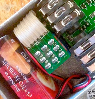
3PDT switches are the main reason why a pedal stops working. A broken 3PDT switch can cut your sound, and the pedal is not easy to switch on and off. 3PDT (and switches in general) are mechanical devices that suffer when activated a lot of times. Usually, good quality switches are rated for 30 000 cycles, but with the way we treat our pedal (kicking them all the time on stage), they usually fail sooner than that. Moreover, most of the times, we do not use good quality switches, but rather “China Blue” 3PDT that are not that reliable (but way much cheaper than Alpha switches).Replacing a switch is easy but sometimes quite annoying, as you have to rewire everything. To make replacement easier, you can use 3PDT miniboards and ribbon cables. This system is used in many commercial pedals, like in Electro Harmonix or even Diamond pedals:

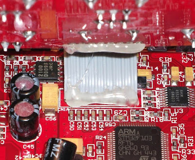
But what if you just want something more reliable? Another solution is to use relays instead of 3PDT as a mechanical system to switch the signal. A normally open momentary soft switch can be used with a microcontroller to drive a relay to switch the signal. Indeed, relays are rated for way more cycles than mechanical 3PDT. For instance a Panasonic TQ2-L 5V, which is a classical relay is rated to last between 10 and 100 million cycles! The momentary switch is really easier to replace than the 3PDT switch, only 2 cables to solder. Here is an example from the Dr Scientist Bitquest pedal (great brand!):

2. Wiring dessoldering
When wiring the pedal, cables are not always really fixed, and the solder can break and cause a disconnection in your wiring. This can happen quite easily on the 3PDT jack where there is a lot of wiring going on, or even on input jacks. It can make the pedal mute, or generate a huge amount of noise if there are grounding issues arising from a dessoldered wire. It is easy to fix (just ressolder the wire), but quite annoying if the person cannot fix it at home (no soldering iron…etc) and needs to send the pedal over. There are two ways to prevent that. The cheap way to do it is to apply a kind of glue on the soldered wires to avoid physical stresses that cause unsoldering. This is the case in this Caline pedal (Chinese cheap clones):

3. Loose jacks and 3PDT
This is a classical problem. Input jacks and the 3PDT can sometimes become a bit loose, even if you tight them with a pair of pliers. In the worst case scenario, the nut or the bolt can be lost in the process, and the pedal would be quite difficult to use if the input jack or the 3PDT “enters” inside the enclosure… It is really easy to fix, but it is a very common problem, and quite boring to repair because the customer would have to send it over (or I would have to send screws to repair it) just to fix a loose jack. There are two ways to avoid this: either your tight it a lot with a pair of pliers, either you can include jacks directly on the PCB.However, it has one downside: if the jack input is not working anymore, it is quite boring to replace because dessoldering and ressoldering of the jack is not easy. So, do not forget to use high quality jacks like Neutrik NMJ6HCD2, and not to overcrowd the PCB around the jacks to make dessoldering possible.
I am designing my first “commercial” pedal, and I plan to include the jacks directly on the PCB. It avoids a lot of wiring (reason 2), and prevents loose jacks.
4. False contacts
If you let your PCB “free” in the enclosure, or just wire it without solid core wire (bendable wire), the circuit board can move in the enclosure. Sometimes, it can create false contacts that are quite boring to fix because you never know where it comes from. Also, it happens a lot with veroboard, where the copper side can make false contact with the bottom of the enclosure. The classical "spaghetti wiring" of beginners is also quite dangerous for that...
5. Component failure
Actually, I have never seen a component failure per se. Most of the failure I observed resulted from a power supply mistake. The most common case is with MAX1044 (voltage inverter / voltage doubler IC), that can only accept 10V maximum. If someone tries to apply an 18V voltage for instance, the chip simply stops working. Another thing that happens is when someone uses an inverted voltage on a pedal using a normal voltage (polarity inversion). Usually, the diode that protects the pedal from it usually just burn / melt and has to be replaced. Here is an example of a melted diode:
For the MAX1044, I use a socket so it can easily be replaced. For the diodes, I use a “long legs” package on my PCB so I can just cut the legs of it, which makes dessoldering easier. Also, SMD components are much more difficult to replace, so I would advise to avoid it.
There it is! This are the 5 main points I noticed concerning guitar pedal failure. I am sure that you can spot other things that make your pedal fail, do not hesitate to tell me by posting a comment!
If you like this article, thank me by liking the Coda Effects facebook page, or by subscribing to the newsletter!

3 Comment
Hi Benoit, im waiting for your relay bypass version
Answerwith or without microcontroller, as long as friendly with 1590A/B. hehe
Hello ! The relay bypass is working (on my breadboard), I am now working on the PCB. I will probably make 2 versions of the relay bypass : with or without input jacks. The version with the mounted jacks will be for 1590B enclosures
AnswerFor the Max1044, I use a socket so it can easily replace.
Answer