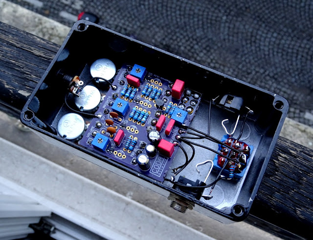
I named it "Black Hole" because of the antimater doom riffs it can generate :)

If you are interested by the pedal, you can subscribe to the waiting list:
Subscribe to the waiting list
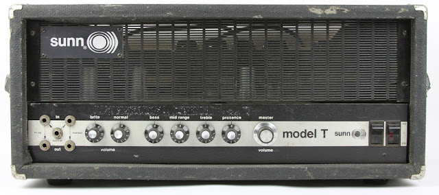
Here is the original prototype. For those who do not know the Sunn Model T, a bit of history...

I was introduced to the Sunn o))) band by a friend a few years ago. At first, I was quite amused by their druid look and fan of the Les Paul of the lead guitarist. However, when I listened to them, I was not really found of it.... Until I saw them live!
It was in a festival in June at the begining of the night. We waited for nearly one hour before the show started, first by envelopping the crowd in a thick mist of smoke.
There was a full row of amps on the stage, and we could distinguish the red warm lights of overheating tubes and standby indicators in the dark.
Then a sound.

And what a sound! I think I have never heard a band play that loud. It make the whole crowd's chest vibrate in rythm with the heavy Nâzgul music played in this mystic mist in the night of June... What an experience! I think the only way to understand this is to see them live, it is a crazy experience that almost looks like a ritual...
Since then, I have becomed quite obsessive with the amp they used to achieved that heavy sound: the Sunn Model T.
History of the Sunn Model T
Originally, the first Sunn amplifier was created in the late 60s by a bass player who thought his amp was not powerful enough for large stages.The first model T was marketed as an amp that could suit both guitar and bass, a 150 Watt beast with four 6550 tubes, inspired by the Fender Bassman 5F6A amp.

There are two channels, a bright and a normal channel. It is possible to use both for maximum gain and power... Guess which is stoner's favorite setting! :)
It has lots of bass and is super loud! No wonder why stoner rock bands like it so much. It is also very rare and quite expensive nowadays, easily reaching a 3,000$ tag price.
A reissue was released in 2008 by Fender, and is also quite rare. Sunn did also issued solid state amplifiers that are quite hyped today as well like the Sunn beta bass.
My version
So I tried to reproduce this killer sound in a box. To do that, I basically reproduced the preamp circuit of the Sunn Model T and replaced the tubes by JFET transistors.It is very different from the Earthquacker Devices Accapulco God that is completely different and simply use a LM1458. The circuit has nothing to do with a Sunn model T, even if it sounds very good.
I made the layout myself, and added a few modifications to have more gain. There is a LPB1 boost before the preamp, that you can switch on or off with a DPDT switch, and tweaked a bit the circuit to make it a bit more gainy,

The preamp is wired with both channels added for more gain. Turning a dial up makes this channel louder, but it is also possible to cut a channel by putting the pot to zero. So you can choose easily between
Good news is: I made the PCB available if you want to build one for yourself:
Through-hole JFET are very hard to come by these days, so I made the layout compatible with SMD JFET. Most of the through hole JFET that are available online are not legit, so I used Fairchield SMD J201 instead. It is however totally possible to use through hole transistors as well.

Even if I made it gainier, it is still very usable as a clean preamp, or as a light drive. It is possible to use it as an overdrive, the JFET are sounding very well for this, there is a nice warm crunch which is quite different from diodes clipping.
The three band EQ is very nice to switch from a heavy bassy drive to a light crunchy drive with more mids and trebles.
When the LPB1 is activated, you go directly in "beast mode", super heavy, almost fuzzy drive that sounds actually quite like Sleep Dopesmoker album
How does it sound?
Here is a short video I recorded to give you an idea of the sound of this little beast!Circuit Analysis
This circuit is basically the original preamp circuit plus the three band EQ and a few tweaks to have more gain, pretty much like the Supreaux Deux I made before.Here is the original schematic:
Basically, I took the top-left part of it and replaced tubes with JFET, with minor tweaks to have more gain, and added a volume stage at the end to have plenty of volume on top.
Here is my schematic:
Let's delimit it in several parts:
First, the signal goes through the LPB1, which is a clean boost in order to have more gain. There is a switch first to choose whether you want it or not, depending on how much gain you need. For a more detailed analysis of the LPB1 circuit, please check this post.
1. Bright channel
The bright channel reproduce exactly the amp chanel 1, replacing the tube by a J201 JFET.
The signal is then amplified with a first JFET transistor, that simply replace the tube in the orginal schematic. The trimpot is used to bias it correctly, the 220uF capacitor increases a bit the gain of it.
There is then a coupling capacitor that prevents any parasitic DC current to get through the circuit, and a Bright pot allows you to set the gain of this stage. The lower its value is, the bigger the signal will be, resulting in more gain later on.
The 470pF removes a bit of trebles as well, increasing the value will result in more trebles in the bright channel.
2. Normal Channel
This is basically the same layout with some minor changes:
I also removed the resistor that bias the JFET, in order to have more gain on this channel. This way, I can achieve a very bassy, saturated sound that is very close to stoner rock standard "Dopesmoker" by Sleep
3.Gain and volume stage
This part of the circuit is where the magic operates!
Then, another transistor re-amplify the signal before it goes through the tonestack.
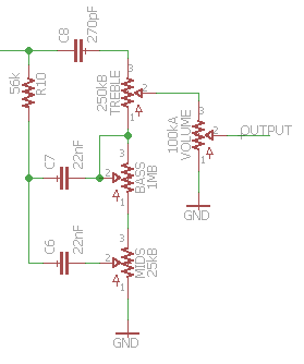
4. Three band EQ
It is a classic passive tonestack that you will find in many other pedal. This schematic was made popular by Marshall amps:
There it is! I hope that you like this blog post! You can follow Coda Effects on the Coda Effects facebook page or on Instagram for more news and infos.
To go further
- Original manual of the Sunn Model T
- History of the Sunn Model T
- Rigs of Doom on Instagram, to see more of them!


29 Comment
I have a modified Sound City to have the Sunn Model T circuit! Very nice for bass guitar as well, sounds like a darker Fender Bassman. Awesome pedal you got there!
AnswerSound City amps are my dream amp #2 (#1 being an old Orange/Matamp...), I love them! Thanks!
AnswerExcellent comme d'hab bravo !
AnswerHello! Have to tried adding a charge pump to this pre-amp? if so, what voltage pump did you find worked best? 17V or 25V maybe?
AnswerHello! I have never tried it... yet! But you are right, it should be interesting to test it. I can test 18V, but maybe not the 25V because of the 220uF capacitor (small voltage rating in order to have a small footprint)
AnswerOK! If you end up testing the 18V output, let me know how it works out compared to the 9V! Thanks!
AnswerDo you happen to have a drill template for your enclosure layout? Thanks!
AnswerYep! Have a look on the build doc ! (link in the sales page here : http://www.coda-effects.com/p/black-hole-pcb.html
AnswerHi!
AnswerI'd better add an output buffer to have a steady impedance source.
Nice job btw.
Exactly. For now, the output impedance is not good enough to use it as a preamp per se. I am currently testing it at my place, and might add it to the v2.0 if conclusive!
AnswerGot mine in the mail a last week, was wondering if there's any concern about soldering near those built-in transistors? Do you have any suggestions for not frying them? This will either be the first or one of the first builds I do, thanks!
AnswerNo problem at all: all the soldering that you have to do is on the other side of the board. They are also more heat resistant that they seem!
AnswerMerci !
AnswerThanks, I bought some Panasonic fc capacitors but the 50v 220uf is way to big for the pcb, I see some 25v on ebay that should fit, is it ok to mix and match voltages? The rest of the electrolytic caps i have are 50v...
AnswerEya! Thnx 4 the lush pedals. Whats the ldr on the board/kit list all about? Light dependant resistor...???
AnswerThe "LDR" part name is actually quite confusing, I was meaning "LeD Resistor", and realize later on it can be confusing! It is just the current limiting resistor for the LED!
AnswerI made your PCB version and it is great! Thanks so much.
AnswerWhat output buffer would you guys recommend?
AnswerA simple Klon buffer usually does the job really well.
AnswerHey! This is sweet. Might get into making one of these later. Do you think that, if pushed into a good power amp, it would sound like a real Model T, with tubes?
AnswerAlso, looking at the original tube schematic, it looks like the tonestack is place somewhat between the two gain tubes! The manner in which looks a little complicated to me, being a novice... Do you think that wiring your tonestack in the middle of the two JFets would be a good idea?
No problem to mix voltage. The voltage only indicates the max voltage the capacitor can handle. For guitar pedals, 25V is largely enough
AnswerTo push it in a power amp, you would need to lower the output impedance with a buffer. A simple Klon buffer does the job really well.
AnswerFor your second question, the tubes after the tonestack is part of the power amp for instance. So not really necessary here.
I mean the tube with the voltage labels 6 and 7, comes before the volume (looks like it should be before the power amp), but also after the tonestack. But on yours, you have Q3 and Q4 before the tonestack and then volume. But if we put the tonestack between Q3 and Q4 would that not be closer to the original preamp?
AnswerOK I see what you mean! The original preamp is organized like this, after the volume knob goes the phase inverter section of the amp. So I decided to follow closely the original schematic. However, I think it would beneficiate from a real output section. For the v2 (maybe next year), I will add an output section that will allow more output volume at lower gain and lower the output impedance.
AnswerHi there, recently bought your JFET loaded PCB to build but was thinking it was a preamp suitable to feed into the Return of a tube (output half of a 12AX7) buffered FX loop in my amp? So is this V1 really for in front of the amp as a boost/dist/fuzz and the possible V2 version a more suitable design for the FX loop Return? Thank you for the PCB. Have you considered doing the Twin Twelve (Silvertone 1484) project in the same way. http://tagboardeffects.blogspot.com/2017/10/jhs-twin-twelve-v1.html http://effectslayouts.blogspot.com/2017/07/jhs-twin-twelve-v1.html
AnswerI might change the name of it until I adapted it for real preamp use. I think for now the impedance is a bit high for that. However if you have a buffer to put next to it, it is perfectly suitable.
AnswerI will do more testing on that.
I am working on a similar desing for a Supro Amp, PCBs are ready but I am block by the J201 shortage
Hello again, thanks for the reply. So I bought a Klon Buffer kit from Fuzzdog (pedalparts schematic), only to find the Manticorefx blog post stating majority of diy Klon buffer kits are 'wrong'. I then found your posts about the PCB you made of a correct Klon buffer. :-( Is your PCB still available? Thought |I'd just use the parts from the Fuzzdog kit, your PCB and a couple of replacement parts with correct values. But can't find the pcb in your shop :-(
AnswerSo in theory just put a buffer pedal after this in the effects loop to use it as a preamp
Answer