Here is the perfect place! I decided to write a full tutorial for beginners, to build an Earthquaker Device Acapulco Gold, step by step. No excuse not to get started!
The Acapulco Gold is a simple, yet very fun pedal to play with, and is perfect for beginners. The circuit is simple and easy to mod as well. With this tutorial, you should be able to build your first guitar pedal!
If everything goes well, you should get a guitar pedal like this in the end:
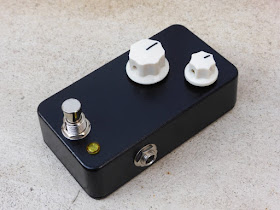
Ready to make your first guitar pedal? Let's get started!
Summary
- "What tools do you need to build it?
- Which components do you need to build the Acapulco Gold clone?
- Veroboard or PCB?
- Populating the PCB
- Drilling the enclosure
- Wiring the circuit
- What to do if your pedal does not work
- Circuit analysis: how does it work?
What tools do you need to build it?
To make guitar pedals, you will need a few tools. Chances are that you already have few of them if you already are a bit of a handyman.I suggest to get them on Amazon. I recommend not to buy your tools in online electronics store for guitar pedals because they usually sell low quality tools.
It is a bit of an investment, but it is really useful in the end. Have a look in your local electronics store. It is also a good idea to buy them used for cheap.
Let's review them.
- A soldering iron. It should be 30W minimum. If not, you will have some hard times to get proper solders. Here is a basic one and a "deluxe" one if you plan on building many pedals. (the Weller soldering iron is a professional grade tool)
- 60% Sn solder. 1mm diameter or less is perfect. This one is very nice for instance.
- Pliers. Simple ones like these will do the job.
- A wire stripper. A simple one like this is OK.
- A drill. We will use it to drill the enclosures. Any one will do the job; enclosures are made in soft aluminum metal, which is really easy to drill. During a long time I used a cheap $15 one!
- A step-drill or drill bits set. You will need the following diameters: . This step drill bits package is nice.
- A round file. Some holes to drill have an unusual diameter. The DC jack is 13mm wide for instance. I use a file to enlarge some dill holes, because drilling with a 13mm is quite hard. A simple one like this is perfect.
More details on my post about DIY guitar pedal tools.
If you are interested in buying a "super deluxe" soldering station, read my review of the Hakko FX888D, which an amazing $96 soldering station.
Which components do you need to build the Acapulco Gold?
Let's go shopping! For this, we are going to take the best components for building guitar pedals out there :)Choose your geographical zone, links will be updated with a local supplier:
North America Europe
I recommend to order most of the parts at smallbear-electronics.mybigcommerce.com, an Brooklyn based American supplier. They have everything we need! Here is my favorite choice of components:
Electromechanical
Capacitors
Resistors
Semiconductors
Hardware
Do not choose a 1590G enclosure that does not fit our usage.
I recommend to order most of the parts at smallbear-electronics.mybigcommerce.com, an Brooklyn based American supplier. They have everything we need! Here is my favorite choice of components:
Electromechanical
- 1x 100k Audio (log) Alpha potentiometer
- 1x 1M audio (log) Alpha potentiometer
- 1x 2.1mm DC Jack
- 1x Alpha 3PDT switch
- 2x 6.3mm Switchcraft Jack
- 2x cool knobs of your choice with an internal diameter of 6.3mm 😎
Capacitors
- 1x 4.7nF (0.0047 uF) Topmay TMC05 capacitor
- 2x 10uF electrolytic capacitor
- 2x 1uF electrolytic capacitor
- 1x 47uF electrolytic capacitor
Resistors
- 1x 1M metal film resistor
- 1x 68k metal film resistor
- 1x 22k metal film resistor
- 1x 10k metal film resistor
Semiconductors
- 1x 1n4001 diode
- 2x LM386-N1
- 2x IC socket 8 pins
- 1x 5mm LED: choose your own favorite color 😃
- 1x 5mm LED bezel
Hardware
Do not choose a 1590G enclosure that does not fit our usage.
It should cost you around $50 in total. If you want to go for others suppliers, you can read more on my guitar suppliers blog post. If you have any suggestions of other suppliers for other regions, do not hesitate to tell me in the comments.
Beware! I know it can be tempting to buy a raw aluminum enclosure to paint it yourself. However, there is very little change that you achieve a nice, professional result I would really not recommend it.
Veroboard or PCB?
If this is your first guitar pedal, I would strongly advise you NOT to use veroboard. Indeed, veroboard is often a cause for non-working pedals. It is really easy to misplace components or to have short circuits. Moreover it requires lots of offboard wiring which can be very confusing.For my build, I will use my PCB. It is of very high quality with gold plated pads (makes the soldering process easier), components are well spaced to make soldering easier. You can find it here:
The PCB connects all the components togeter. If you look closely, you can see the tracks that connects the pads together.

The pads are golden because they are covered with a fine layer of gold. It is not to have the ultimate swag PCB (even if it does look so 😎), but because it prevents oxydization, has a very good conductivity and makes soldering easier!
Populating the PCB
Here is what you should have on your table now: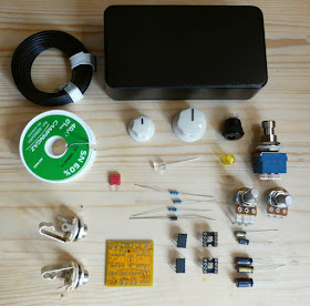
(the 10k resistor for the LED is missing on the picture)
Lets start to solder! Turn on your soldering iron and let's go!
Resistors
First, lets start with resistors. To solder them, bent their legs and place them on the PCB.| Name | Value |
|---|---|
| R1 | 1M |
| R2 | 68k |
| R3 | 22k |
Beware: take your time! It is hard to dessolder components, you'd better not make a mistake.
To make a good solder, follow these steps:
- Clean the tip of your soldering iron with a wet sponge. The sponge should be humid but not completely drawning in water (it will damage the tip of your soldering iron!)
- Tin the tip of your soldering iron with a bit of solder
- Heat the pad of the PCB and the leg of the resistor at the same time.
- Once hot, apply a bit of solder. Apply just enough to cover the pad, not more! Try not to theat the components for too long!
Your solder should be shiny and should cover all the pad of the PCB, like this:

You did it? Cool!
The liquid that is released when you melt the solder is called "flux" and it is perfectly normal! Flux makes the solder flow easier.
If you have difficulties to melt the solder or you find it "sticky" and have a hard time soldering, it might be that your soldering iron is not powerful enough, or that you bought the wrong solder! Check that your iron is 30W minimum and that the solder your bought is 60% Sn.
Now your PCB should look like this:
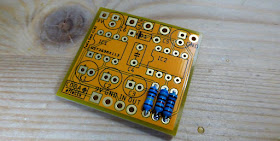
Diode
Diodes have one particularity: unlike resistors, they have a polarity! Pay attention to this when soldering the 1n4001 diode D1.
Beware! Diodes are polarized components and have to be soldered in the good way! A white band shows their positive sides (on large signal diodes) or a black one for small signal diodes. Here is a small diagram:
 So make no mistake!

There you go! Here is how should look your PCB now:

Sockets
We are going to use socket to avoid soldering the LM386-N1. Integrated Circuits (IC) can be a bit fragile and do not like to be heaten for too long.
Beware: you can know the polarity of the component by looking at its notch. Sometimes, there is no notch but a dot like this:


Do not put the IC in the socket yet! We will insert it at the end of the soldering, to avoid any overheating of the IC.
Here is your PCB now:

Capacitors
Let's solder capacitors now. There are six capacitors on the board. Five of them are electrolytic capacitors and C4 is a film capacitor..| Name | Value |
|---|---|
| C1 | 10uF |
| C2 | 10uF |
| C3 | 1uF |
| C4 | 4.7nF |
| C5 | 1uF |
| C6 | 47uF |
Once you are done with it, you can solder the electrolytic capacitors
Beware!
Electrolytic capacitors are polarized components like the diodes and have to be soldered in the good way! There are several indications to find their polarity:
 If you invert the polarity, sound will not go through so make no mistakes!

Now your PCB should look like this:
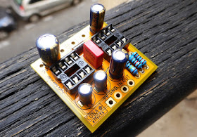
We are almost done!
Check for one last time that your soldering is perfect (no contact between solders, nice shiny solders...):

Potentiometers
Last components to solder are the potentiometers. Let's start with the main potentiometer located on the board, which is a volume pot.First, remove the tab of the potentiometers with pliers:
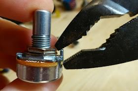
Remember that it has to be soldered on the other side of the board. First, cover the squared pad with solder:

Then, place the potentiometer, and heat it to place it correctly:
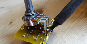
Finally, turn the PCB and add solder to every pad of the potentiometer. Put enough solder to cover the whole pad!
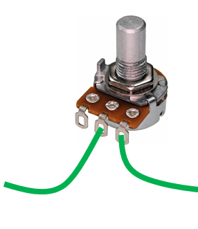
Finally, we have to solder the gain pot. Let's prepare it before soldering it to the PCB in the enclosure. To do that, prepare 2 wires:
- Cut a good lenght of wire (more is better than less!)
- Strip it on each side
- Solder one side of it to the potentiometer like this:
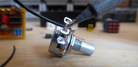
Solder the two right lugs of the potentiometer like this:
Once it is done, we are ready to drill!
Drilling the enclosure
If you want to customize your enclosure, now it is time! If this is your first pedal, I would suggest to keep it like this for now.To drill the enclosure, we first need to print a template. The template will help us not to make a mistake when drilling. It is fairly easy to mess things up when drilling... The enclosure is quite expensive so let's take it slowly!
Once you have print the template, cut it, and tape it on the enclosure. It should fit quite well like this:

Once you have done that, use a nail or anything to mark the emplacement of the holes to drill. Do not drill the center potentiometer as we are making the 2 knobs version.

Finally, remove the paper and check that you can see where to drill. You should be able to see the spot let by the nail:

Usually I use a step drill to make things easier. Here are the diameters for each holes:
- Potentiometers: 8mm (0.325")
- DC jack: 13mm (0.512") - drill a 12 mm hole and then enlarge it progressively with the round file. Check that the DC jack fit or not during the process to avoid drilling a hole too big!
- Input and output jacks: 10mm (0.393")
- 3PDT: 12mm (0.472")
- Led bezel : depends on the model you chose. Generally, the diameter to drill is indicated on the sales page.

Let's go! Take your time and go slowly. Aluminum is easy to drill so no big deal here! Your enclosure should end-up like this:

Perfect! Now we are ready for the last part!
Wiring the circuit
This is the part where beginners often make mistakes! Take your time and check everything.
We have now to connect everything together. First, put everything in the enclosure: PCB, gain potentiometer, input and output jack... It should look like this:

Now, we have to connect everything using wire. Here is a schematic of what we want to achieve:
To do that, estimate the length needed for your wire, cut it (with a comfortable margin), and strip the ends of it with a wire striper.
Let´s start with the small wire of the 3PDT. Make a small wire like this:
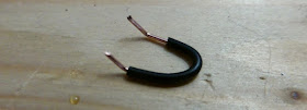
Then, place it in the 3PDT and solder it:

In a general way, I would recommend to prepare the wire and place it before soldering anything.
Now, lets prepare the grounding. Ground is the reference 0V voltage. If you do not connect all grounds together, your circuit will probably not work or be very, very noisy. On the PCB, ground is indicated as GND. The jack inputs and the DC jack also have a ground connection.
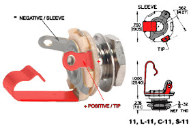
Here is the jack connections. The negative sleeve is the ground connection, and the positive sleeve will transmit guitar signal.
Cut the wires and dispose them in the enclosure like this:
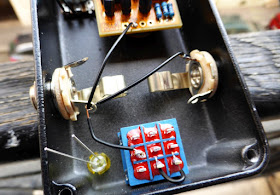
Then solder it. Apply a lot of solder on the jack inputs. You want to fill the hole where the wires are inserted.
Now, lets go for the DC jack. Here is its polarity:

Connect the 9V to the 9V pad on the top of the PCB, and do the same for the ground.
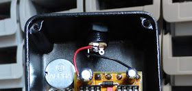
Follow the schematic above and connect everything. Take your time!
Here are a few tips for the LED. You see that we have to connect a resistor between the 3PDT and the LED. The best way to do that is to prepare the resistor and start by soldering it on the LED.
Bend the 10k resistor like this:

You can now solder it on the minus side of the LED. Pay attention on the polarity of LED!

Once you have solder it on the LED led, cut the other leg of the resistor to the appropriate length and place it in the 3PDT. Finally, solder it. It should look like this:

Once you are done with the resistor, you can solder the 9V wire to the other side of the LED. Same technique as above, first twist the wire:

Place it on the positive side of the LED and solder it:
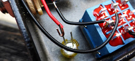
Place the other side of the wire in the 9V pad on the bottom of the PCB and you are done!
You know how to wire now, you can do the rest by yourself. Just follow this schematic:
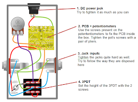
More tips about guitar effects wiring on this blog post.
Once you have solder the jacks and the potentiometer, you are done!
Here is the inside of the final pedal, do not forget to place the ICs in there, following the right polarity:

You can now test it on your favorite amp!
What to do if your pedal does not work
Benoit! My pedal makes no noise at all 😥Do not panick!
I like to say that electronics never work on first attempt. Even after building more than hundred pedals, I still make mistakes and some of my pedals do not work right after soldering!
First, check that your wiring is correct. It is the part where beginners makes most mistakes.
If your wiring is OK, just follow this list:
- Did you inverted input and output jack? (more common than you think!)
- Did you made a mistake in the wiring?
- Did you make a mistake with one component? (pro tip: do not forget to put the ICs in the sockets 😁 )
- Re-check the wiring!
I know this can be frustrating. If you cannot find the solution, post a comment!
Circuit analysis: how does it work?
OK this thing is cool sounding and all.... But Benoit, how does it work?Let's dive in.
The circuit is organized around the two integrated circuits LM386N-1 (IC1 and IC2, the two triangles on the schematic below). What happens here is very representative of what happens in a lot of guitar pedals.

Have you ever tried to push the sound of a device too loud? For instance, if you set your laptop volume to 200% (possible on VLC), with volume maxed out, you will hear that your sound is not really good sounding at higher levels: it is distorded! That is exactly what happen in this little stompbox.
In electric guitar, that is exactly what we do when we add saturation to our sound. However, we try to make saturation sound as musical as possible (and that is why we still use tubes: the way they saturate is really musical).
Depending on the electronic component used, the way it distort will be very different:
- Germanium transistors have a reputation to distort nicely, whereas silicon ones can sound a bit harsh (which can be nice in some fuzz circuits)
- OP amps can distort very differently depending on their internal architecture.
- ... but tubes are still the golden standard for distortion. It is so musical that they even like its distortion in the HiFi world!

As you may know, guitar signal is an AC voltage, which amplitude determines volume and frequency its pitch.

The term "gain" just mean how much the signal will be amplified. A gain of two means that the volume will be doubled.
A first OP amp will amplify your signal a lot, so much that it is impossible for it to amplify it. Indeed, in the Acapulco Gold, the first OP amp have a gain factor of 200, meaning the OP amp tries to make your guitar signal 200 times louder!
Here, it is the LM386N-1 that saturates and create this massive sound. That is why the volume increase is also so crazy. In the end, you sound is still amplified by a huge gain factor!
So now that you got the general idea, let's go in the details. First, lets divide the circuit in several parts:

Power Supply Filter
This part of the circuit just aims at resolving two things: polarity inversions and noise.
If there is a polarity inversion, the diode 1n4001 will let current pass and prevent it from going into the circuit.
It is very common for power supplies to have residual ripples of 50Hz from your power outlet in the 9V DC provided to your gear, that can generate noise in your circuit. The C6 capacitor will absorb excess of current provided by the power supply, and provide a bit more current when the power supply lacks a bit of voltage.
Input Stage
This stage goal is to amplify the guitar signal in an extreme way to make it saturate.
The C1 capacitor is a coupling capacitor. Coupling capacitors are used to prevent any parasitic DC current to go into the circuit. Indeed, capacitors only let alternate current go through them. The bigger the value of coupling caps, the more bass they will also let through. 10uF is a huge value for a capacitor, meaning all the bass content of your guitar will be amplified too.
If you find your pedal too bassy, it is also an easy way to decrease bass content: replace the coupling caps by lower values like 22-47nF.
R1 is called a pulldown resistor, and is used to increase input impedance of the circuit. It also helps to prevent "pop" noise when you activate the pedal (which is very common with high gain circuits like this one).
Then your signal will go though the first operational amplifier, from pin 3 (input) to pin 5 (output).
C3 is another coupling cap with a big value to let aaaalll the bass go in the next stage.
Filter
The problem when you amplify a signal is that you amplify all the frequencies, including the ear-piercing treble content of your telecaster guitar. 😭This stage reduces the treble content of your amplified signal with a simple RC filter to prevent that.

R2 and C4 form what is called a low pass filter. It will prevent high frequencies to go through the next step of the circuit. They are very common in guitar pedals to adjust the tone of an effect.

You can calculate the cutoff frequency by a simple calculation:

f = 1/(2 x π x 68 000 x 4.7 x 10-9)
f ≈ 498 Hz
498 Hz is a fairly low cutoff frequency, meaning few trebles will go through this filter. It gives to the pedal is heavy, bassy feeling, and avoid having too much trebles in the final sound.
Changing R2 by a lower value allows to have more trebles. You can also replace it by a 100k potentiometer to have a tone control!
Output stage
The output stage re-amplies a bit the signal and is used to set the final volume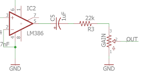
The IC2 OP amp have a gain factor of 20. The signal is again amplified. C5 is a coupling capacitor again.
R3 aims at lowering a bit the volume. Indeed, when your signal goes through a resistor, it loose a bit in amplitude.

Finally, the "GAIN" potentiometer is used to adjust the volume (confusing, I know). When you turn the potentiometer, its resistance value changes and thus changes the amplitude value of the output signal. Read my post about potentiometers for more about it.
There you go! I hope that you now have a working pedal and that you understood how it works!
If you have any question or comment, post a comment below! If you like this post, thank me by liking the Coda Effects Facebook Page. You can also follow Coda Effects on Instagram.

This comment has been removed by the author.
ReplyDeleteHow wonderful! If only I could have had this tutorial when I started making pedals!! I would have saved a lot lot of time! Very very nice work Benoit! Thank you!
ReplyDeleteThanks for the kind words. I really hope it will help beginner to get started and enter the marvelous world of DIY guitar pedals
DeleteHi!
ReplyDelete>If there is a polarity inversion, the diode 1n4001 will let current pass and prevent it from going into the circuit.
And will probably burn itself, unless there is a series resistor at the input of dc socket, or power supply has some sort of a fuse (poly fuse or protected voltage regulator).
I'd add some sort of small resistor in series with dc input socket, around 10-30 ohms, or replace it with 100mAh resettable fuse, or place protection diode in series, not in parallel.
DeleteThat's right, however power supplies have an internal fuse so it wont happen because you are basically making a short here.
DeleteHowever, you are right, it might be safer to use a zener diode in series with the circuit.
Really good. Good explained and detailed. Greetings!
ReplyDeleteA power diode like a 1N4001 in series with the power line will drop the voltage by whatever the forward voltage drop is on the diode, around 1.5 to 1.7 volts, typically. If you put it across the 9V and ground in reverse bias, it will do nothing to the incoming power unless you hit it with reverse polarity or AC, in which case it will protect the downstream components much like putting a crowbar across the V+ and ground lines. If you use the crowbar-style protection, there should be a fuse or circuit breaker in the V+ line to prevent overheated power leads and a fire hazard.
ReplyDeleteYou can probably use a low value series resistor in the power line to limit current to say, 100mA at 10 volts. That would be a 100 ohm resistor.
ReplyDelete100mA at 10V is 1Watt of power, so the 100 ohm resistor should be 2W or larger. Place it in the power line before everything else.
ReplyDeleteNew to pedal (and playing guitar in general). Great description of how the device works for electronics newbies. I was wondering however - under the heading diodes you mention that the white or black bands are on the positive side, yet the illustration shows them on the negative side.
ReplyDeleteThis schematic is really helpful, thanks! A few questions that would help -
ReplyDelete1. Where would the power input go in this schematic?
2. Where would the LED fit in?
Trying to recreate on a bread board and play with the resistor values as noted to try to get the hang out things. Thanks for the awesome write up!
Hi Benoit!
ReplyDeleteI just finished up my build and (after fixing some obvious mistakes :P) I found that when engaged, my pedal just issues forth a very mild humming with rhythmic popping/clicking (it's very subtle). I'm going to take a rest and come back to this.
My one note, is that I have currently skipped the LED and will add it after I've fixed any issues and seal it up. Could that be the source of the issue?
Thank you!
Why IC2 has a gain of 20?? Where ar the resistor for gain?? I would like to understand, thank you so much
ReplyDeleteHello Benoit!
ReplyDeleteI just finished my build (without the volume mod) but I noticed some popping when I turn it on and off. How can i fix it?
Great walkthrough!
ReplyDeleteCould you please clarify the text "A white band shows their positive sides" regarding diodes, isn't it the other way around. The band marks the cathode/negative side?
Hello and thank you! What may I do to not have plug power in and just use a 9v battery?
ReplyDeleteAmbient style guitar tones can be so saturated in effects that it may often be difficult for the beginner's ear to distinguish rhythm and note definition. DigiPedal.com Great pedals for making your guitar sound super lush and wide sounding.
ReplyDeleteWow, esta pagina es oro puro.... y lo mejor es que lo encontre cuando apenas me estoy adentrando. Muchas gracias por toda su aportacion que es de bastante ayuda
ReplyDeleteRegarding solder, I'd recommend Kester 63/37 no-clean solder (.015".) It has a very narrow "plastic" range and makes very pretty connections.
ReplyDeleteDone it a thousand times. 10k is too much for LDE current limiting. I like bright ones at aroind.3K9
ReplyDeleteJust an FYI. Link to the IC chip is incorrect.
ReplyDeleteThis has been SUPER helpful! I set this up on a breadboard and it worked perfectly. I feel like I have a better understanding of what everything does except C2. Can anyone elaborate on what its purpose is between pins 1 and 8 on the first IC?
ReplyDeleteI just finished assembling the Coda Effects Fool's Gold and I am very happy that, being my first build, it produces at least some sound!
ReplyDeleteIt's a nice and really fun pedal to play at most settings, but anyway I hear some problems when cranking out the left knob near the max: it seems the sound "is breaking" in some way. This is a short clip https://sndup.net/4236 to help you better understand what I mean. at different pedal settings but you'll hear the problem I refer to around 1:55 in.
What could be the source of the problem and how could I fix it?
I am waiting for a capacitor that I'll use to build an audio probe, but until then I thought maybe someone can share some hints.
Here https://imgur.com/a/8tHrIv6 there are a couple of gutshots, just to give you an idea of what's inside - again, not the cleanest job, but at least it (almost) works!!!
Thanks!