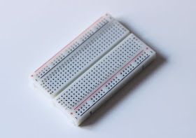
Well, we have a simple solution for that: using a breadboard!

Let's go! In this blog post, we'll see why the breadboard is such a cool tool and how you can use it to design and test your own circuits.
What is a breadboard?
And why do we call it like that?Yes, "breadboard" really comes from the word "breadboard". 🍞
In the old times, people were using a wooden plank (the "breadboard") with nails to connect the components and test it. Like that

Don't worry, we are not going to do that.
We will use a modern version of the breadboard, which looks like that:

How does a breadboard work?
Components can be inserted in the little holes on the board; which are then connected to each other as follows:
The side strips (indicated in red and blue here) are connected along their entire length. We usually use them for ground and power supply connections! That is why they are often called "power rails". On some breadboards, there is even a "+" and a "-" to make things easier.
Shorter horizontal strips are used to insert components and connect them together. The middle ravine separates the two side and allows you to put integrated circuits in the middle.
Tutorial: let's make a boost on breadboard!
Let's practice and make a simple boost on breadboard: the LPB1!You will need
- A breadboard of course. This kit is just amazing. You will have jumpers and a PCB to connect power supplies easily to your breadboard.
- Jumpers. You can use solid core wire and make some yourself.
- Two 0.1uF film capacitors
- One 2n5088 transistor
- Four resistors: 430k, 43k, 10k and 390R
- A logarithmic 100k potentiometer
- Two jack inputs
- A 2.1mm power supply input
First, we need to look at the schematic:

Simple circuit, no? Keep it somewhere near, we will follow the signal path to make our circuit.
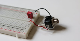
First, let's start with the power rails. Solder some wires on the DC power supply input and the jack inputs. We will place the power supply in the power rails like that:

It will make connecting the component to ground or 9V very easy.
Than, connect the jack input to ground, and place the input to the first 0.1uF capacitor:

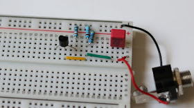
Then, we can place the two 430k and 43k resistors that bias the transistor. The 43k one is connected to ground, whereas the 430k one is connected to the 9V power rail. Here, I have replaced them with a 470k and 47k resistor, but it is the same layout:

Let's now place the transistor (be careful of the polarity!). A jumper connects the signal to the transistor's base (center pin). The 390 ohms resistor is connected to ground.

As you can see, it can get crowded pretty fast, even with a simple circuit. It is important to organize the components and cables properly, otherwise you will quickly have a "spaghetti wiring"...
Let's connect the last capacitor to the left pin of the transistor. The 10k resistor is connected to the 9V power rail:

Finally, we can add the potentiometer. The left pin is connected to ground with a jumper:

Output jack:

And there you go, you have a functional LPB1! You can now test it directly with your guitar and amplifier! It can be a little noisy because of the loose connections, but you can hear how it sound without having soldered anything! 😃
As you can see, it is quick and fun to do. Moreover, it is super simple to test mods like that! Just replace a component by another value and see for yourself!
Here is a simple circuit guide to test some mods:
With a breadboard, you can also easily test to mod a part of a circuit. For instance, you can test different tonestacks of a Big Muff circuit by simply replacing the components values!
I hope this was useful to you. Post a comment for any question!
If you liked this article, thank me by liking the Coda Effects facebook page! You can also follow Coda Effects on Instagram.


Excellent starter's guide, thanks for posting it!
ReplyDeleteThank you!
ReplyDelete