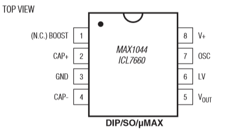
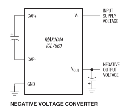
For that, it uses a MAX1044 integrated circuit, which can invert the supplied voltage. Here is the schematic that we can find on the datasheet:


The voltage enters the chip through the V+ pin (number 8), and goes out inverted through the number 8 pin. The pin number 3 is connected to the ground, and a 10uF capacitor is connected between the cap+ (connected to the + lug of the cap) and cap- (Guess which side of the cap ^^). A 10uF is connected to the ground near the output voltage.
The power supply can be also a bit improved with a simple layout that you will find in many stompboxes. It is present in Scruffie's layout (without the 0.1uF capacitor)

The diode connected to the ground protects the circuit from polarity inversion. Indeed, the diode only let the current goes through in one direction (following the arrow of the scheme of the diode). So if we plug a classic center negative power supply, the ground will be 0V, and +9V will be +9V. No current will go through the diode. However, if we plug a center positive power supply (which can happen with fuzz faces that usually need center positive power supply), the ground will become +9V, and the voltage will be the ground! In a normal context, this would damage the components, and specially the transistors... However, here, the current will go through the diode straight to the +9V (ground), avoiding such trouble (quite annoying with NKT275 transistors, which worth almost 30 euros!)
The 100 ohm resistor, combined with the 47uF and 0.1uF capacitors eliminate all the residual oscillations that come from the power supply. Indeed, when the current is converted from alternating to direct, some ripples can still be there. As the capacitors only let the alternating current go through them, the alternate current will go to the ground instead of parasiting the circuit and generating "hum" noises! The different values of the capacitors are here to eliminate high and low frequencies of alternating current.
In the end, with this simple layout, we get an input voltage that is more stable (less noise), and a protection if someone plugs in the wrong power supply (center positive instead of negative). Which can happen with Fuzz Faces!
I hope that everything is clear! If not, post a comment!
To go further:
Geofex from +9V to -9V: an ingenious system to use the battery only when a jack is plugged in.

1 Comment
Just a small correction: "The voltage enters the chip through the V+ pin (number 8), and goes out inverted through the number 8 pin." - Output is pin 5, here.
AnswerAlso, many thanks for your amazing work!