Showing posts with label Builds. Show all posts

JHS Superbolt clone PCB and the missing JFETs

Hello solderers and pedal maniacs!

Here is my last build: a JHS SuperBolt clone! As you may know, I have already did a clone of this pedal, but I have finally designed a PCB for it!

Here are some pictures:

JHS Supebolt clone 

I used a Supro logo that was laser-cut with some double tape to make the "Supro" sticker. I think it makes a really nice look!

JHS Supebolt clone

Development Hell: multiple fuzz pedal

Today, I am going to introduce the concept of Development Hell: it is a special place where projects stay when they need a lot of fine tuning before properly work. Unfortunately, I have a few projects that are still burning there, like the one I am going to present today.

It is a multi-fuzz machine! I always felt that a lot of Fuzz are quite a "one trick pony", they have a very characteristic sound that can be modulated by mods, but still sounds "like a fuzz face", "like a big muff"...etc. Moreover, fuzz are usually quite simple circuits, and I find that allowing one spot per fuzz on a pedalboard can quickly be space-inefficient.

So I decided to create a multi fuzz pedal, with no more than 3 different fuzz inside : a germanium Fuzz Face, a Muff Fuzz and a Companion Fuzz, which should provide the 3 main "flavors" of fuzz in this world: a classic warm, soft fuzz face, a "chainsaw", very raspy Companion Fuzz, and a compressed and heavy Muff Fuzz.

On top of that, I added an upper octave generator that allows to combine it with any fuzz, with a potentiometer to adjust the amount of octave. It is based on the Green Ringer circuit, which is a small, but efficient analog octaver circuit.

And of course, I made it fit in a 125B enclosure...

Here it is in its current form:


Tonebender MKIII clone (Aion Electronics Phobos)

Here is my last build: a Tonebender MKIII clone! The tonebender was initially a derivative of the Fuzz Face, a bit closer to an amp distorsion than a fuzz. (read my post about the different types of fuzz) It became quickly famous thanks to a lot of guitarists like Jimmy Page or Jeff Beck.

The MK2 version used two germanium transistors to get fuzzy tones. However, due to the nature of the circuit, the quality of the fuzz was very dependent on the transistor's gain and characteristics, just like in the Fuzz Face. In order to avoid the selection of transistors, the Mk3 version used 3 transistors, so that the quality of the sound is less dependent on the germanium transistors used. Here is my version:

Tonebender MKIII clone Aion Electronics Phobos

Boss Tap Tempo DIY

Here is my latest build, a very simple tap tempo pedal for a Boss DD7 pedal (or any other pedal with external tap tempo). It is very simple : one mono jack, one momentary SPST! Very easy build, I think it is the perfect build to begin with DIY! Tap tempo is very useful if you play in a band, so I think this is really a great way to improve your beloved DD7 guitar pedal.

I used a Hammond 1590LB enclosure, which is really small. However, I did not centered the momentary switch because of the lack of space.

Boss tap tempo pedal

Other Vemuram Jan Ray variants

Since I designed my own Jan Ray circuit board, I assembled quite a few. The PCB is quite small, so I have made different variants of various sizes and colors, and I though you migh enjoy it. Here are some of them!

Here is a Jan Ray in a beautiful "mirror" copper color:

Tap tempo tremolo DIY: a complex project!

I am currently prototyping a tap tempo tremolo that I conceived. It is quite a big project, and I have been working on it since nearly 6 months now! Like many guitarists, I really like the warm vintage sounds that you can achieve using tremolo (like in "Bang Bang" from Nancy Sinatra), but also the choppy madness that you can get with square waves, like in "Know your enemy" from Rage Against The Machine, or even weird stuff with high speed tremolos... A really cool effect!

I play regularly in a band, and my point of view is that tap tempo is just absolutely needed for rhythmic effects like delays for instance. Thus, I decided to add one in my tremolo. It is not easy to implement a tap tempo, as you have to use digital circuitry, as we will see later... Here is my current prototype:
DIY tremolo with tap tempo
That is a lot of knobs! You can already notice that there are two footswitches: tap tempo (right side), and the true bypass footswitch that is a clickless relay bypass system! I used the relay bypass system that I conceived, which is completely silent, and more reliable than classic 3PDT true bypass. Indeed, 3PDT footswitches are the main reason for guitar pedal failure. The little switch in the middle of the two LED (bypass LED, and tempo LED) allows you to switch the pedal temporarily. This is nice to add some choppy stuffs while you play!

Black Arts Toneworks Pharaoh Fuzz clone

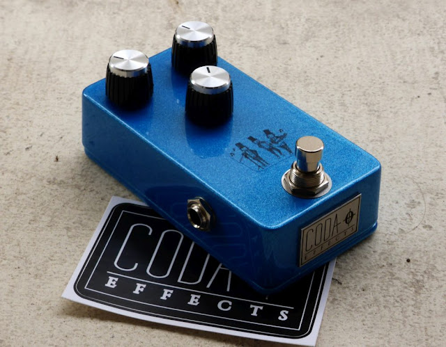
I want to make  Big Muff variants using my Coda Effects Big Muff PCB, and show you how to make them yourself. Lets start with the boutique version of the Big Muff that made it popular again on the stoner / doom scene: the Pharaoh Fuzz! Produced by Black Arts Toneworks since 2011, it was an immediate success because of the huge, warm, doomy sounds it can produce.

Here is my version:
Pharaoh Big Muff clone
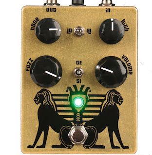
As you can see, the Pharaoh has more controls than a classical Big Muff. There are the classic gain / volume / tone controls, like a classical Big Muff, plus a few other options. Here is the original version of the Pharaoh:
Black Arts Toneworks Pharaoh Fuzz
There are a "high" potentiometer that allows us to set the amount of trebles, and two switches. The first switch is a 'high / low' switch, that allow us to have 2 types of gain settings for the pedal: low gain and high gain. It modulates also a bit the trebles. Finally, you can choose the type of diodes in the last distorsion stage with the second switch: classic silicon diodes, no diodes or germanium diodes!
Black Arts Toneworks Pharaoh Fuzz clone
Finally, there are some modifications on the circuit. For instance, input and output capacitors are 10uF tantalum capacitors, which will let a looooot of bass go through the circuit!

Here is a gutshot (yes, I had fun drawing this!):
 Black Arts Toneworks Pharaoh Fuzz clone
You can see the tantalum capacitors that are drop-shaped. I try to avoid as much as possible to use it in my guitar pedals. They are not especially good for audio, expensive, and most of all there are not really "ethical friendly". Tantalum is produced from coltan, a mineral that is the root cause of many conflicts, especially in Congo. Illegal mines were opened without any regulation, degrading environment in an uncontrolled way, with many Human right issues (a bit of reading about that on wikipedia). Traceability is a big problem with electronics. Most of the time we do not know how, where or in what ecological context components are made... For tantalum capacitors, just know that they are easily replaceable by electrolytic capacitors.

Wima capacitors are much better for that: they are made in Germany (and thus, their production must respect European ecological laws and regulations). This is why I try to use them as much as possible:
 Pharaoh Fuzz clone
So, how can we make the Pharaoh from a classical Big Muff PCB?

Here is the schematic from the Big Muff page:
Pharaoh Fuzz schematic
As you can see, it is very similar to the Big Muff circuit! We can use the Coda Effects PCB and modify it following the above schematic. Here are the modifications to do:
- no mid knob, 470k for R5.
- no R2 resistor (we will use a switch instead)
- no D1/D2 diodes (switch here too)
- no R8 resistor. (replaced by a "high" potentiometer)
No big changes!

If you want, Rullywow sells a PCB especially conceived to make the Pharaoh Fuzz, named "King Tut". If these mods seems a bit difficult to do, you can buy this PCB to make it easier ! Rullywow creates really nice PCB, and this one is no exception, and is of very nice quality.

First, we will remove the mid knob by placing jumpers on the mid knob pads, like indicated on the build document.

To include the switches, we will have to use a 125B enclosure, it will not fit in a 1590B. We will have to use long lugs potentiometers to place switches so they do not touch the circuit board and create false contacts.

For R2 and D1/D2, we will use switches:
- SPDT on-on for choosing R2
- SPDT on-off-on to choose D1/D2 diodes.


Choosing R2: switching between the Hi/Lo setting of the Pharaoh

We use a "on-on" SPST. Signal arrives to the center of the switch, and goes through a resistor, 39k ("high" setting), or 390k ("low" setting):
Pharaoh mod
Try to make the connections on the other side of the PCB, it will be simpler. With this switch, you can choose the R2 value! In "high" position, there will be a lot of gain and trebles, whereas in "low" position, the sound will have more bass, less trebles.

It can apply to any resistor in the circuit, so feel free to experiment! Of course, some resistors are more interesting than others... I let you try!


Diodes choosing: 3 positions switch

We will use the same system for the diode switch. We are going to use a 3 positions on-off-on SPDT switch in order to have: germanium diodes (3 to have assymetric clipping), no diodes or classic silicium diodes. The second set of diodes to replace is D1/D2:
There it is! We have our two switches. Beware of false contacts with these switches: try to reduce the length of naked cables.Voilà ! On a déjà nos deux switchs !


Treble potentiometer

Last mod to add to have exactly a circuit like the original design: the treble potentiometer. In fact, you just have to replace R8 (tonestack resistor) by a 25k potentiometer. Just connect the lug 1 and 2 to each pad of the R8 resistor:
Pharaoh mod
It can also apply to any resistor! You can investigate to find your favorite resistor to modulate ;)
There it is! Voilà! We have got our Pharaoh Fuzz PCB!

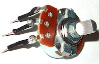
You can solder the other potentiometers now.  Beware: if we use "classic PCB-mount" potentiometer, the switches will not fit in the enclosure (they will touch the PCB and create false contacts). We will have to use "long lug" potentiometers like this ones:
long lugs potentiometer
You can also use classic potentiometer and make the lugs longer with soldered wire with solid copper wire or cur resistors / diodes lugs for instance.
long lugs potentiometer solder

You can now drill the 125B enclosure, and rock! :)
Have fun!

To go further:
Official Pharaoh webpage : if you are interested in buying the original pedal
Veroboard version of the pharaoh: a bit annoying and complex to make, but doable!
King Tut PCB: dedicated PCB conceived by Rullywow

Dead Astronaut FX Chasm Reverb

Remember my Dead Astronaut Chasm Reverb PCB? I finally finished it! I left it quite a long time aside my bench, mainly because I did not have time or money to buy and build all the remaining things that needed to be done. Remember, if you want to have one, you can buy one directly from Dead Astronaut, or buy the PCB to make it yourself.

Here is my build: 
Chasm Reverb Prismatic dead astronaut
I used a prepainted enclosure, with a nice vintage color vibe, close to Surf Green color. With cream knobs of course! I just miss a cream pickguard part to have to most vintage fender look!

As I already said before, it was a fun build to make. The PCB is quite big and components are well spaced, so it is really easy and fun to build it, even for a beginner. I had absolutely no trouble at all. I did a few mistakes with the wiring, which is not a common wiring scheme as the pedal is buffered bypass. Apart from these minor incidents, the pedal almost worked immediatly, nice!
Chasm Reverb Prismatic dead astronaut

There are four potentiometers: volume (to set the output volume), mix (allows you to mix the dry signal with the reverb signal, you can go from a 100% dry to a 100% wet signal), damp (set the overall brightness of the reverb) and decay (set the amount of reverb that goes to into a feedback loop). Indeed, one of the features that make this reverb unique compared to other Belton Bricks reverb out there is that a part of the reverb signal can go through a feedback loop, allowing the reverb to auto oscillate! The switch allows to put the reverb in auto oscillation mode.


How does it sound?

I finally invested in proper recording gear (Senheiser e906 and external audio card), so I manage to record something for you! The Chasm Reverb is a deep, spacy sounding reverb, very good sounding with a delay!

The volume potentiometer is useful if you make it oscillate. At max, it is normal volume level, and you can lower it. The Mix is also quite useful, although I do not really like a too wet sound. The oscillation switch is really killer.

You can make the reverb smoother, and create "waves" of sounds, that lush for a quasi illimited amount of time! It is really awesome when combined with a delay! Perfect for ambiant stuff, and you can leave it on on the background.


Circuit analysis

Here is the circuit, from the build document:
Dead Astronaut Chasm Reverb Schematic
If you have already read the circuit analysis of the Rub A Dub Reverb, you can already find some similarities. As most of the DIY reverbs, it uses a Belton Brick, an IC that allows DIYers to make reverbs without having to use a spring reverb tank.

It is divided in several parts:
Dead Astronaut Chasm Reverb Schematic
Let's analyze each part of the circuit.


Power supply

The power supply is a classic one that we can find in many circuits. It provides 3 different regulated tensions:  9V, 4.5V and a regulated 5V.
Dead Astronaut Chasm Reverb Power Supply
The Zener diode (D6) prevents polarity inversions. R22 and C16 forms a low pass filter that will eliminate any 50Hz parasitic voltage ripples remaining from your AC outlet.

R23 and R24 forms a voltage divider that provides a 4.5V tension (VB). It is regulated by C17, a 47uF capacitor that will absorb excess of voltage. This tension is necessary for the OP amps to operate correctly

Then, there is a voltage regulator, REG1, that is a 7805. "78" means that the output tension is positive, and "05" is the output tension, 5V. The regulator is necessary to supply the Belton brick a good voltage. Unregulated voltage could result in damaging the IC that is very sensitive to higher or lower voltage drops, and so requires a regulated tension provided by this small chip that look like a transistor! You will find this kind of regulators in almost every circuit using numeric IC.


JFET switching buffer

This is a peculiar switching schematic that is very pratical here because it allows the use of a buffered bypass setting that make reverb trails possible. In a true bypass setting, the reverb would be cut abruptly when the effect is turned off, whereas here it can slowly decrease
JFET switching schematic circuit
So how does it work?

First, there is an input buffer, formed with R1, C1, R2 and the first OP amp of a TL072. As you can see, there is no resistor in the loop of the OP amp, thus it has a gain of 1. It is just used to transform the low impedance signal from the guitar into a low impedance signal.

Then, ther is the proper JFET switching. Here, JFET transistors are not used like amplifiers, but rather like "on / off" switches (like in computers!). When the JFET is turned on (by supplying 9V through the DPDT switch), it allows the signal to go from the drain to the source: the signal can pass. When a JFET is on, the other is turned off, so the signal either goes to the effect, or to the buffered output. A diode prevent any parasitic signal from the gate to enter in the signal path.

This switching scheme is nice with a reverb: it diminishes "popping" issues, and allows reverb trails, which is super nice with this reverb and its auto oscillating feature.


The Reverb circuit

The reverb circuit uses the Accutronics reverb module, a great integrated circuit that I presented already in the Rub A Dub Reverb circuit analysis.
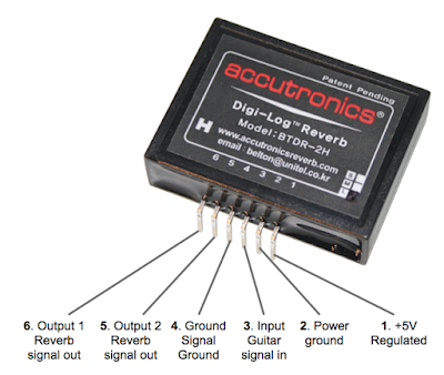
Here is a schematic of the BTDR-2H that is used in this circuit:
Accutronics BTDR 2H Belton Brick
There are 6 pins on the brick. The two first ones are used for the power supply. Note that the power ground is supposed to be different than the signal ground. In some circuits, that is very important to separate digital and analog ground, and to combine them in only one point in order to diminish noise (especially if you combine digital chips with analog ones like MN3005 that are also in 5V).

The guitar signal enters in the third pin (signal ground on the 4th pin), and is "transformed" by the chip in a reverberated sound that goes out at the 5th and 6th pin. The reverbarated sound is not the dry sound + reverb sound. It is just the reverberated sound, so it is kind of peculiar. You have to mix it with the dry signal to make it sound like a reverb.

Here is the schematic of the reverb:
Dead Astronaut Chasm Reverb schematic

So first, there is a MOSFET input buffer, that increase a bit the signal. The signal is then split in two. A part of it stay dry (Dry signal part), and the other is treated by the Belton brick (reverb signal), they are mixed in the end with a mix potentiometer so you can set the amount of dry signal versus the amount of reverberated signal.

The dry signal just goes through this section without being modified, and goes to the mix knob.

The reverberated signal is buffered by an OP amp (TL072), with a gain of one (so no gain basically). A 100pF capacitors in the loop rolls off a bit of highs, and the signal can enter the BTDR2H brick. The signal then goes out from pin 5 and 6 of the reverb. The high are roll off by a low pass filter formed by the "DAMP" potentiometer and C5. For more infos about low pass filters, read my post about the Big Muff tonestack. Thus, you can set the amount of trebles in the reverbarated sound. Then, the reverbarated sound goes through an OP amp in a similar layout than at the entry. The signal then goes to the mix knob.

If that were the only features of the Chasm Reverb, this reverb would be a simple reverb with a tone control. What makes this reverb unique is its feedback loop. A part of the reverberated signal can go in the feedback loop and goes back to the entry of the reverberation circuit. The amound of signal going back to the begining of the circuit is set by the Decay knob and the switch that let you choose between a 47k resistor (a lot of signal goes back: oscillation) and a 100k one (less signal goes back: more a long-decay like reverb). This is really cool because if you set a high decay, a lot of signal can go back in the reverb circuit, and it can actually autooscillate! It also allows to approximately set the decay of the reverb, which is not possible with a standard BTDR2 brick.

After the dry and reverberated signal are mixed with the "mix" knob, there is another knob, that acts as a master volume knob. It is wired as variable resistor, and acts as a classic volume knob. The signal (reverb + dry) can now goes through the output buffer.


Output buffer

The output buffer is a simple buffer using a single OP amp from a TL072 chip.
Dead Astronaut Chasm Reverb schematic buffer
A 100pF in the loop rolls of a bit of highs. If the pedal is off, the dry signal goes through it with a gain of 1 (resistor R16/R13), but if the pedal is on, it has a bit of gain (R15/R16) to compensate the loss of volume due to the Belton Brick, the mix and volume knobs. It is a simple buffer, very transparent because of the high values of the coupling caps (C10 and C13, 10uF) and the use of the TL072.

There it is! I hope that it is clear and that it was helpful! Do not hesitate to ask questions in the comment. If you like this post, thank me by liking Coda Effects Facebook page!


To go further

JFET switching (pdf by Geofex): great explanations about JFET switching, around the classic Boss / Ibanez circuit.
Accutronics BTDR2 official webpage. 
Pedalrig tips about noise, great infos too!
Chasm Reverb official webpage, if you want to buy a built one or a PCB!

Jan Ray in a 1590B with Coda Effects PCB!

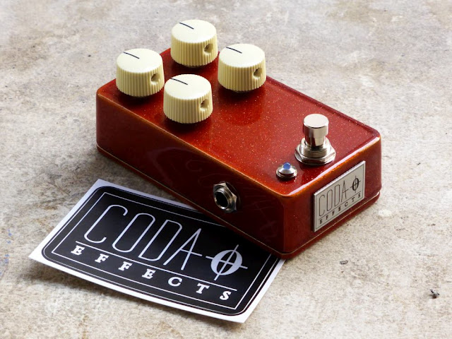
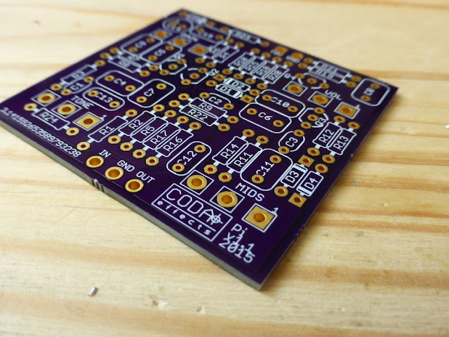
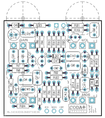
Here my latest version of the Jan Ray! This time, instead of the 1590BB or the 125B version, I made a smaller 1590B version, using a PCB that I designed! 

The Jan ray is quite annoying to make on vero, mainly because of the four knobs to wire. A PCB is thus quite helpful to make it easily. Moreover, it allows me to fit it in a 1590B enclosure. Here is the finished pedal:
Vemuram Jan Ray clone

I used the same look as before, with vintage orange sparkle prepainted enclosure, except that it is a 1590B now :)

 Make one yourself

It is quite a simple and fun build to do

Vemuram Jan Ray clone 
I also used a sticker to name it: Golden Hour (vintage overdrive). Photographers will understand! I think it gives a really nice look to this pedal. 

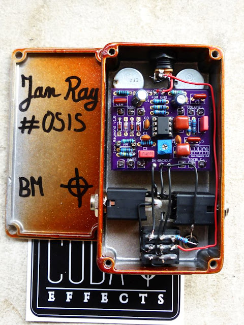
Here is the gutshot:
Vemuram Jan Ray clone
It is the classical circuit of the Jan Ray, with the OP amp, and trimpo for bass content / overall gain. I just changed a few things: R4 is 1.8k instead of 3.3k. This mod allows you to have low gain settings, nice if you want to use this pedal as a clean boost, or just to modify your sounds. Playing with the pedal, I realized you can "stratify" your sound easily by adding trebles and removing bass. Sounded very good with my P90 guitar.

Another modification I did was to replace the OP amp (LM1458) with a Burr brown OPA2134. I think it "soften" a bit the saturation. A nice touch to it.

I am currently testing other mods, with the diodes (LED, compressed...etc.), treble filter (to have less trebles maybe), gain of the last OP amp (too much volume for me on this pedal)

I just made a circuit guide of it to help you understand what does what. The Big muff page has this kind of circuit guide, and I find it very helpful. I hope that you like it, let me know what you think!
Jan Ray Timmy schematic circuit guide
If you want to experiment, socket the component you are interested in modulating, and try different values! Read the circuit analysis I made for more infos.

Sound samples !

LPB1 boost

Remember my LPB1 PCBs? I finally built one! As the PCB is quite small, I decided to make my first 1590A build. Here it is:
LPB1 boost clone 1590A
Simple one knob boost, with quite a lot of gain. I used a 2n5088, which provides already quite a lot of gain. It is a simple volume boost, quite transparent that can be used to make your amp saturate a bit more, or to simply increase the volume of your guitar if you use it in your amp loop.
LPB1 boost clone 1590A
This is my first 1590A, and everything went better than expected. I was afraid that I would not have enough space inside such a tiny box to make all the component AND the circuit fit, but it was OK.

Some advice to make it easier:
  • Use PCB mount 3PDT. They are a bit smaller than "normal" 3PDT and let you a bit more space.
  • Use semi-enclosed jack like Lumberg KLBM3 jacks. They are a bit smaller and easier to use than open jacks like the one I used.
  • use 9mm pots.
Madbean pedals has issued a very nice guide to explain you all the tricks and tips about 1590A builds (pdf). I managed to make it, not the most impressive 1590A build ever, but nice though:
LPB1 boost clone 1590A

How does it sound?


Well, it is a simple clean boost. So you can either use it as a volume boost in front of your amp (if set clean), or in the FX loop, or to increase the gain of your amp if you have set it crunchy. You can also use it before a dirt pedal to increase the saturation of it.
I am planning on testing it in front of different builds. I already tried it in front of a Jan Ray build, making it basically a Tim, nice to have 2 gains settings in one pedal. I also want to try it in front of a Big Muff, like in the Musket Fuzz... I think it can fit in approximately any guitar pedal!


Circuit guide


I already did a circuit analysis of the LPB1 booster. However, I realized that sometimes, it is easier for beginners to understand the role of each component with an infographic, like the circuit guide of the Big Muff page.
Here is the one of the LPB1 booster :
LPB1 circuit guide schematic

Let me know if you like this kind of representations, I can try to update old circuit analysis with circuit guides like this one!

Big Muff circuit going to fab!

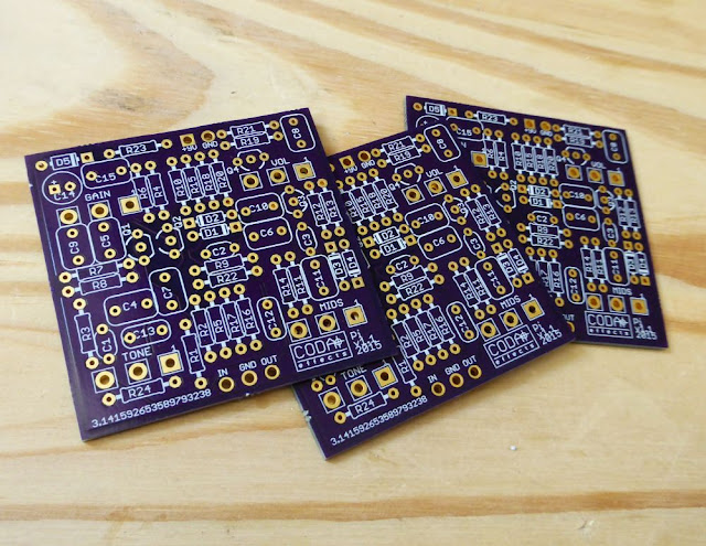
Here is my new Big Muff PCB!Big Muff PCB
Remember when I was telling you about PCB development? (yes, long time ago...) I finally finished one! It took me a lot of time, but now I am satisfied with my layout:
Big Muff PCB layout
As some of you recognized, this is a Big Muff circuit! I decided to add an optional forth knob: the mid knob. I can decide whether I want to add it or not, simply by adding a jumper if not (and then, the tone potentiometer can be wired in the center of the pedal). Maybe I will add another optional feedback mod, allowing to connect Q1 emitter to Q3 emitter via a switch. It creates a nice noisy feedback, ideal for sound experimentations...

The circuit is exactly the same as a classical Big Muff, I just added the mid knob in the tone stack, and some components for polarity protection and voltage stabilization. (on the top-left part of the PCB) I will rename the components so their number will be the same as the one used on the Big Muff Page, so you can easily make any version of the Big Muff you like, or modify it with their great circuit guide.

Capacitors sizes were chosen bigger than needed, so they can be swapped with other value to fit any Big Muff model (Russian, Ram's Head, ...etc). Note the funky logo I made because OshPark is not able to use imported images...  Anyway, it is still nice!

I receive the first batch of prototypes:
Big Muff printed circuit board

It is a very compact build! It can fit a 1590B enclosure (well, I hope so...), or at least a 125B with top mounted jack. For now, I ordered a test batch of 3 PCB in oshpark, and I plan to test it as soon as possible! If it works correctly, I think I will produce a small serie of PCB.

    As you may know, PCB are cheaper if ordered in large quantities. If you are interested in buying one PCB (or more!), send me an email, so I can adjust the number of PCB I will order! Price will be around 5-8 euros for the first batch (depending on the number of people interested), with a 1 euro shipping cost for France, and 3 euros abroad.

I first designed this PCB for personal use, but it can be a win-win situation if people are interested.

For now, I am thinking about the logo I will use, I thought of this:
I noticed that the "Pi" symbol, looked like a lot a Dolmen... Which is also convenient for a Fuzz that has been used by many stoner guitarists, including ones disguised as druids (Sunn o))), anyone ?). Maybe I will have it laser cutted in black or red (maybe purple for a "violet era" rams head), in order to have 2/3 different version. A bare aluminium version with the red logo that will be the "vintage correct" version, following a classic 73 ram's head fuzz schematic, and a black logo on a black or dark green (russian) box for a "doomy" version, very bassy and gainy.

Let me know what you think about it, post a comment!

Black Keys's Big Muff: dealing with mids frequencies

Another Big Muff clone! This time, I was inspired by the Black Keys (if you do not know this band, go check it out, it is awesome!). Dan Auerbach, the guitarist/singer, uses a lot of fuzz effects, and especially a green russian Big Muff, and a Earthquaker Devices Hoof (a Big Muff variant with some interesting modifications as we will see later).

So I decided to basically mix these two variants in one Big Muff! Here it is, a 4-knobbed Big Muff:


LPB1 mini PCB !

The LPB1 (Line Power Boost 1) is a boost pedal that was commercialized in 1968 by Electro Harmonix. It is the first boost pedal using a silicon transistor. Indeed, previous boosts like the Dallas Rangemaster Treble Booster were using germanium transistors. Another novelty with this pedal was that it was boosting all frequencies and not only trebles, making it the first clean boost available!
 vintage 1968 LPB1
The circuit is really the most simple one you can imagine for a boost:
LPB1 schematic
First, there is a 0.1uF coupling capacitor that prevents parasitic DC current from the guitar to go in the circuit. With the R2 resistance, it forms a high pass filter : by changing its value, you can modulate the amount of bass going through the circuit. If you increase C1 value, more bass will go through, and vice versa.

Then, there are two resistors forming a voltage divider (R2 and R1), to provide a certain voltage to the base of the transistor. Here it is : R2/(R2+R1)x9V = 43/(43+430)x9=0,81V at the transistor's base.

The silicon transistor is a 2n5088 (originally a 2n5133 - same transistors that were used in the Big Muff later), wired as a common emitter. R4 and R3 will define the amount of amplification. If you increase R4, amplification will be larger. If you increase R3, there will be less gain.
A second 0.1uF coupling capacitor that prevents DC current from the battery to go out of the circuit. Finally, a 100k potentiometer wired as a variable resistor defines the final volume.

If you look carefuly, you can see that the last stage of the Big Muff circuit is exactly the same! A LPB1 circuit is used to increase the final volume.

Indeed, this circuit can be used in a lot of different effects to boost the entry or final level. A fun thing to do is to add a LPB1 boost before a saturation effect to increase the gain. It is very fun on a Big Muff (like in the Musket Fuzz or Supercolider fuzz), or on a Tube screamer (like in the Fulltone Fulldrive)!

In order to be able to add this little circuit when I want, or to test it on several pedals, I decided to make a small PCB that allows you to add a "boost" knob on every pedal you want. There is a "in" and a "out" pad that allows you to place it anywhere in a circuit:
EHX LPB1 PCB line power boost
I will test it on a Big Muff or a Jan Ray! I could also try to see if it can fit a Hammond LB enclosure (super small squared enclosures like the one I used for my Strymon Favorite switch) Note that there is no voltage stabilization or polarity protection system on this board (too small, not enough space for it!), so do not hesitate to wire a 100uF capacitor between the two lugs of your power supply input.

I should receive all the parts to test it soon...

Klon Centaur Clone and mods (Aion Refractor)

The Klon Centaur is one of the DIYer's favorite pedal. Indeed, the original version of this mythical overdrive actually costs more than 1500 euros! This pedal is more like a legendary unicorn than a real pedal that you can test one day... Even the reissue, the KTR, which is not hand assembled costs more than 300 dollars... The amount of clones (aka "klones") of this pedal has grown insanely over the years: JHS, Rockett, ARC Effects, Electro Harmonix with the Soul Food, almost every pedal manufacturer has issued their clone, always closer to the original pedal.

Summary

For those who do not know the Klon Centaur yet, it is an overdrive created in the 90s by Bill Finnegan and MIT engineers (yes!), that is probably the "hypest" pedals of all. It was used by many guitarists, including Jeff Beck for instance. It is a three potentiometers overdrive: gain, volume and trebles, famous for the light crunchy tones it provides to your sound. It has also an excellent reputation as a buffer or clean boost. In fact, I have already made Klon buffer PCBs to use it in a patch box.

Recently, different PCB makers made Klon Centaur PCBs available, so you can make your Klon Centaur yourself. I used a PCB from Aion Electronics, the Refractor overdrive. This PCB is amazing, a fantastic work has been done by Aion Electronics to make the circuit fit a 1590B enclosure ! If you want something a bit bigger (for instance if you want to make a Klon-like look), you can use the Madbean Sunking PCB. I also wanted to see if there were audible differences between my EHX Soul Food and a replica of an original Klon Centaur (without the goop ^^).

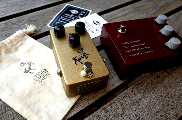
Here is the result!
Klon centaur clone
I used a prepainted enclosure from Banzai Music, in a classic gold color to make it look like the first golden Klon centaur pedals. I used a stamp to "print" a centaur on the enclosure with China ink. Then, I varnish the enclosure. I used a french website, called tamporelle, to make a custom inkstamp. It was very quick, and the stamp is of really good quality. Plus, it is quite cheap. I really like the result, it is not really easy first, but after a few tries it looked good!


I also used my laser engraved plate on the front side of it.
Klon centaur clone
To compact the Klon circuit in a 1590B enclosure, a fantastic work has been done by Aion Electronics. The PCB is very compact, yet quite easy to populate because it uses classic components, and you do not have to place resistors vertically. The PCB is of excellente quality, double sided of course. The guide made by Aion Electronics to help you to build it is really detailed and well done. If you want to make a small Klon clone, I really advise you to use this PCB.

However, it is not an easy build. The compaction of components is quite high, and you have to be quite precise when drilling the enclosure. Fortunately, the build document is really complete, and you have a drilling template included. Mine worked directly on the first attempt (This is a rare thing when building pedals...) !

Klon centaur clone aion electronics refractor
I decided to build a replica of the original Klon Centaur circuit. I used tantalum, electrolytic and film capacitors like it was on the first Klon Centaur pedals. For that, I used the document realized by Martin Chittum from freestompboxes.org in 2009. Indeed, the original pedal is gooped. Goop is a kind of black resin that embed the circuit and components, and prevent you to trace the circuit. The freestompbox community decided to buy a Klon Centaur, and sent it to Martin Chittum who managed to "ungoop" the circuit and trace the schematic of the Klon Centaur, and report precisely the components used.

The only point that remained elusive after this work was the kind of diodes used. They were germanium diodes of unknown nature. Some tests determine that the diodes had a 0,35V voltage drop, which matches russian D9E diodes, that I used for my Soul Food mod. I used these diodes in this build:
D9E diodes klon centaur
However, Bill Finnegan himself recently anounced that he used 1N34A germanium diodes in the original Klon Centaur:
    "The diode I have always used is a germanium diode with the part number 1N34A, but you should understand that this particular part has since the 1950s or so been manufactured by literally hundreds of different companies, and having listened to as many different ones as I have, I can say with confidence that they all sound somewhat different in my circuit, and often they sound VERY different." -Bill Finnegan, The Gear Page forum post-
These are really basic germanium diodes, quite surprising for these mythical diodes! The D9E are old soviet diodes, so it is true that managing to grab some of them in 1991 (when Bill started to develop the circuit), two years only after Berlin wall's fall, must have been difficult! Moreover, the marking is different between the soviet diodes (blue mark on the anode) and the diodes that you can find in the Klon Centaur (black mark on the cathode). For me, it is probable that diodes used were 1N34A, but maybe as he is saying these diodes were from a batch that sounded a bit different from more recent 1N34A... D9E sound good to me and have the right measured voltage drop anyway, so I'll keep using them.


How does it sound?


As you may know if you know me or follow my blog, I am really sceptical about the Klon "mythical" reputation. My Soul Food seemed like a good reproduction of the sounds delivered by the Klon, and I did not really get the buzz around this pedal. It is a nice clean boost, and good for really light saturations, but was a little too trebly for my ears. With more gain, the pedal becomes really "transistor" sounding, and quite boring... Finally it became more my boost pedal than a true overdrive pedal.

So I started to test the pedal without great expectations. I have to admit that I was surprized! If the pedal really sounds like the Soul Food in low gain settings (really nice for light crunchy riffs), the high gain settings sound really nice with the Klone!

It is very dynamic and powerful, yet quite transparent, with some added mediums and trebles that makes you want to play big crunchy solos! I understand better the setting that Jeff Beck uses on his Klon Centaur:
Klon Centaur Jeff Beck pedalboard
(gain pot is on the left)

I am really surprised... I will do a blind test to be sure that my brain is not playing with me, but it seems like there are differences with high gain settings.

The pedal was compared to a Klon KTR, and sounds are really close, no audible difference between them. Proof that everything is about circuit and components, and not mojo and magic!
Klon clone vs klon KTR 
You understood, it is really close to the KTR. If you want to have an idea of how it sounds, listen to demo video of the KTR. I will try to record samples as soon as I get gear for recording audio samples.
Coda Effects Klon clone vs Klon KTR
I am currently making a small serie of 5 pedals to buy some gear to record proper video and audio samples... Send me an email if you are interested.


Circuit analysis


The Klon is a rather complex circuit. It is quite weird because there are lots of informations and tests about this pedal online, however there are few informations about how the circuit works precisely. I have to remind you that the circuit was mainly conceived by electronics engineers from the MIT (and not by Bill Finnegan, who tweaked it more than conceive it), and thus, the circuit is quite "non-standard" compared to classic overdrive circuits (Tube Screamer, Rat Distorsion...etc). So brace yourself, winter is co... lets analyze this!

If you are not very familiar with the different components, and the theory around guitar pedals, I suggest that you read a few articles about theory and other circuit analysis before reading this one!

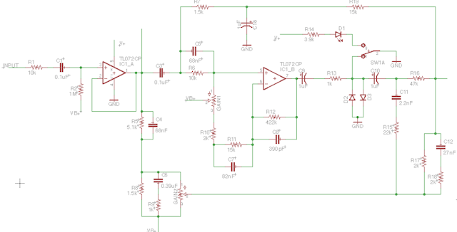
Here is the famous circuit:
Klon Centaur Schematic

You can already see that, contrary to many overpriced "bouteeek" pedals, the circuit is not a tubescreamer, and is entirely original!

So we can already see 4 operational amplifiers (OP amps), the famous germanium diodes between the second and third OP amp. If we try to see where the signal goes, we can see that there are several pathes that the signal follows, we can see that the signal is divided between clean and saturated, and then mixed again. When the pedal is "off", the signal still goes through the top part of the circuit.

I traced the path followed by the signal:
Klon centaur schematic circuit analysis signal path

We can see that the bypass signal (blue) is splitted in two: clean and saturated signal (green and pink, respectively). The amount of each splitted signal is dosed by a double potentiometer, the gain potentiometer. So basically, drive and clean signal are mixed, which allows really light and low saturation mimicking an amplifier just at the break up. If the Klon is so good with light drives, it is surely thanks to this mechanism that allow to have very slight saturations mixed with your clean signal.

You can also see that when the pedal is off, your signal can still go through an OP amp (it is the blue loop at the top of the schematic)... It is the famous buffer!

If we divide the circuit in different sections like we are used to, it can be this:
Klon Centaur schematic circuit analysis
Finally, in the bottom right corner, you can see a power supply section using a MAX1044, that allows to have different tensions in the circuit. If you remember, the MAX1044 integrated circuits can be use to double a tension, or to invert it. Here, both of these functions are used!
Lets see this part of the circuit first!


1. Klon Centaur power supply

As you can see, there are no more than 4 different tensions delivered by the Klon Centaur power supply! We have V+ (9V), VB+ (4,5V), V- (-9V) and V2+ (18V)! Simple circuits are for the newbies lel!
Klon centaur power supply schematic
V+ (9V) is stabilized using a 47uF capacitor, and a diode (D4) prevents polarity inversion. It is the classical power supply scheme.

V+ is then divided by two using a voltage divider with R29 and R30, to have VB+ (4.5V). If you do not know what a voltage divider is, read my post about resistors and their role in effect pedals. This tension is also stabilized with a 47uF capacitor (C18).

Finally, the MAX1044 is used to have an inverted tension (V-, -9V) and doubled (+V2, +18V). The MAX1044 is an integrated circuit sold by Maxim, that allows to transform tensions. Here, it is used as indicated on the datasheet (as simple as that!). For more infos about the MAX1044, read my article avec voltage doublers.


2. Klon buffer analysis

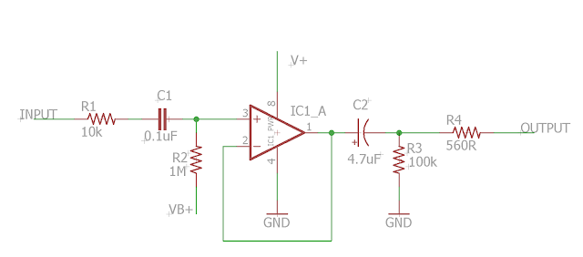
The blue loop on the top of the circuit that goes towards the output of the circuit is only active when the pedal is "off". It is the famous buffer! A buffer has a high input impedance, and a low output impedance, so that high frequencies are maintained all along your signal chain. Here is the scheme of the klon buffer:
Klon centaur buffer schematic
(remembre, I designed a PCB to make it)

The first part, until C2, is simply the circuit input. There is a resistor at the input of the circuit (R1), and a pulldown resistor to avoir "popping" noises when the circuit is turned on. For more infos about pulldown resistor, read my article about resistors in guitar pedals.

The C1 capacitor is a coupling capacitor: it prevents parasitic DC currents from the pickups to go in the circuit. With R2 resistor, it also forms a high pass filter. If the value of the capacitor is bigger, you will allow more bass to go though the circuit. Here, with a value of 0.1uF, most of the bass of the guitar will go through the buffer, so the buffer will be transparent!

Then, the signal enters the OP amp, first one of the TL072CP. The TL072 is a double OP amp, very transparent. It is wired in non inverter (signal enters the OP amp through the + input). Usually, they are some resistors to define the gain of the amplifier, here, there are none. Thus, the gain is around 1, which allows you to have the same volume at the input, and the output. The OP amp has a high impedance input, and a low impedance output: the buffer diminishes the signal impendance, and maintains the volume!

Finally, there is a 4.7uF coupling cap, combined with a 100k resistor connected to the ground. This is a high pass filter (again), that will let almost all bass frequencies go through it (again). A last 560R resistor will adjust the final volume, and the signal gets out of the buffer.


3. Signal splitter

When the circuit is "on", the signal does not goes through the buffer, that is disconnected from the circuit by the footswitch, but through a "splitter". This part of the circuit splits the signal in two: clean and saturated signal.
Klon centaur splitter
At the input of the splitter, there is the beginning of the buffer circuit. Instead of going to the top partof the circuit, the signal can now take several pathes: down through the 5.1k resistor and the C4 capacitor, go through the second OP amp, or can go through the R17 resistor... What is this mess?

These different splitters selects some specifics frequencies. Unfortunately, I am not good enough with theory to tell you which ones... It involves rather complicated calculations with Fourier transforms and all... If any talented personn could help me with that, it would be awesome!

Lets focus on the bottom part. The signal goes through different components (R5, C4, R6, C6 and R9), then goes through the GAIN2 potentiometer, that set the maximum . You can see that the signal does not goes through any diode clipping system, so this part of the signal stays clean. In the end of the loop, it is mixed with the saturated signal.

The clean signal can also go through the top part of circuit, with the 1,5 and 15k resistor. It adds a bit of clean signal in the end that is mixed with the GAIN2 clean signal and the saturated signal, in order to always have a bit of clean mixed with the saturated signal, even when GAIN2 is maxed.

Finally, the remaining signal goes to the input of the second OP amp. A GAIN1 potentiometer set the amount of signal going into the amplification loop of the OP amp. GAIN1 and GAIN2 are in fact one double potentiometer: when the value of one increase, the other one increase! Thus, it doses the amount of clean and saturated signal to mix together: the more saturated signal, the less clean signal! It is an unique feature that is not present in any other pedal, and this is one of the novelty brung by the Klon Centaur: a part of the signal is kept as is, and the other part is saturated. Thus, the overdrive is really good for low drive.

The saturation comes mainly from the OP amp saturation. Another thing that is not usual with classic overdrives circuits! It has quit a high gain. We can calculate it. It is wired in non-inverter, so the gain will be 1 + loop resistor / resistor to ground = 1 + 422 / (15 + 2  + value of the 100k potentiometer  = 1 + 422 / (117) = 4,6 with the lowest gain, and 1 + 422 /  (17) = 25,8 when gain is maxed.

Then, there is a coupling capacitor (C9), and signal arrives towards the famous germanium diodes D2/D3. Most of the times, with moderate gain, these diodes are useless! I could test that with my soul food mod. They only are important when the gain is set up pretty high.

Finally, at the end of the splitter, all the signals are mixed again together.


4. Output signal mixer

Here we are, this is the last part of the circuit, the "signal mixer"!
Klon centaur output stage
The two signals that were mixed at the end of the splitter are going to be amplified and filtered a bit.
A first OP amp wired in inverter amplifies the signal. This OP amp has quite a high gain, that insures a high volume gain, useful if you want to use the Klon as a boost. This is where the incredible amount of volume of the Centaur comes from.

A second OP amp with a gain of 2 (look at the values of R22 and R24) will allow to set the final amount of trebles in the output signal. It is a classical high pass filter: you let the signal go through until a certain frequency, defined by the C14 capacitor. Decreasing the value of this capacitor will let more treble go through. A common mod is to increase the value of this cap to have less treble (we will see it later). The amount of trebles that can go through this cap is set by the treble potentiometer.

Finally, a 4.7uF coupling capacitor prevents parasit DC current from going into the last section. A 560R resistor the volume potentiometer will define the final volume of the output! There are also two resistors, R27 and R28, but I have to admit that I have no clue about their role... if anyone knows?

There are still things that I do not really get with this circuit... I guess it is a little bit overcomplicated. I would love to understand the splitter in details, but I am still lacking some precious filters knowledge...

I hope it still gave you an idea about how the circuit works. If you have any question, do not hesitate to post a comment. Lets have fun now that we know the circuit: what can we mod?


Klon centaur mods and tweaks


The Klon centaur circuit can be modded easily to modulate the gain, bass response or diode clipping. Lets see a few Klon Centaur mods together:
  • Increase C14 value: it is a very common mod to set the tone response a bit better. It allows a bit more bass to go through and make the Klon less "thin sounding". I usually use a 6.8nF capacitor, treble pot is thus more useable.
  • Separate the dual gain potentiometer in two pots: instead of using a double potentiometer, you can split each parameter with two 100k potentiometers. You can choose how much clean signal you will blend with the overdrive sound, or use only the overdrive part of the circuit. It is also useful for bass, if you want to let more bass goes through the circuit. I guess that the blend potentiometer on the bass soul food comes from this mod.
  • Diode clipping switch: you can choose between two sets of diodes with a simple DPDT switch. This is what I did with my Soul Food mod. There are not much changes between germanium and silicon diodes, however LED gave some nice results. There is much more headroom, it feels a bit like a distorsion!
  • Bass switch (madbean "fat" switch): this switch will affect the amount of bass that goes through the second OP amp. To do that, we can add a switch to choose between the 82nF stock capacitor and a 150nF one for C7.
    Klon bass switch mod
  • Bass contour mod: instead of using a switch, you can use a 50k potentiometer to blend the higher value capacitor in. You can also use a bigger value like 220 nF or even 1uF! However, you can see that this mod is only acting on the saturated part of the circuit, and not on the clean signal that is blend later. Thus, it is more hearable with high gain values... To have a proper bass knob, you can try to use a double potentiometer, and blend a higher value capacitor in parallel of C4 (68nF) too! I have never try that, maybe I will give it a shot at one point.
    Klon bass potentiometer mod
  • Using different OP amps: instead of the TL072CP, you can use different less noisy OP amps, or more "classic" overdrive OP amps. The simplest solution is to use sockets for OP amps, and try any double OP amp IC that you would like. To test: LM1458, OPA2132, LF353, JRC4558D... Any double OP amp can give you interesting results!
  • Increase gain: to have more gain on your unit, you can modify R10 resistor. It has a 2K resistor originally, and you can use a lower value to have more gain, or even a jumper!
  • Using the Klon Centaur with a bass: if you cant to use the Klon Centaur with a bass, you can change a few values to let more bass going through  (from Madbean pedals): C1, C3, C4 : 220 nF, C5 : 100 nF, C6 : 1 uF, C8, C13 : 1 nF, C7 : 330 nF, C11 : 6,8 nF, C12 : 56 nF, C14 : 15 nF. I also strongly suggest to separate the gain and blend knob (second mod), so that you can dose how much bass will go through the circuit. The Bass Soul Food actually uses this mod. Here is the traced scheme for our bassist fellows:
Klon centaur for bass schematic
  • 1994's specs switch: in 1995, Bill Finnegan slightly modified the circuit (see below). Most of the changes were not affecting the sound, except the addition of R11 (15k resistor), that was supposed to boost a bit the bottom mids. If you want to hear what that does to your tone, you can put a switch there to choose between the 15K resistor or a jumper.
I will try to do some videos of some of these mods.


Klon centaur versions


Aestheticaly, the enclosure design changed a bit around the production time. Lets do a bit of "klonology" (chronology, get it ?! OK, I'm out...)
Klon Centaur versions
Gold and silver klons were produced at the same time, however the silver Klon was introduced in the early 2000s, and the graphics changed a bit with time. Three graphics can be considered: no centaur, big centaur with "open tail", and small centaur with closed tail. There were 5 different colors: 4 different gold colors (that you can see on the picture above), and the bare polished aluminium color (aka "silver" centaur). Around 8000 Klon centaurs were made between 1994 and 2009 according to Bill Finnegan (1.5 Klon centaur a day!). All those Klon worth today more than 12.000.000 euros!

First, there are no differences between gold and silver centaurs. The circuit and component values are exactly the same. Hearable differences should be really low and due to component's tolerances (Bill Finnegan used carbon film resistors with a 5% tolerance,  capacitors with 20% tolerance, so you can expect some slight variations from units to units)

Concerning the electronics, contrary to many other guitar pedal lines (Big Muff...), no big changes happened over time. The first version produced in 1994 lacked the resistor at the beginning of the circuit (R1), had no ground plane, and missed the R11 resistor. All these changes were processed in 1995. The 15k R11 resistor was added to have a bit more low-mids response. However, if you try to remove, the changes are incredibely subtle...
    “The fact is, under the hood they’re all basically the same. In 1995 I made three small changes: I added a resistor to give the circuit some protection against a static charge delivered to its input—a change that has no sonic effect. I also had the circuit board redesigned with a ground plane for better grounding—again, no sonic effect except the potential for a little less hum. And I added a resistor to give the circuit a very small amount of additional low-mid response—I wanted it to have a little more roundness when used with, say, a Strat into a Super Reverb. I made no other changes.”   - Bill Finnegan, Premier Guitar interview -
Another change noticed by Manticore FX is that another resistor was added at some point at the end of the circuit. It is R28, a 100k resistor that is present just before the switch. I do not really know its role, if you have any ideas...

The KTR version was issued in 2012. It basically has the exact same circuit as the Klon centaur, and the same diodes for clipping, but it was intented for mass production. It uses surface mounted devices (SMD), so the production could be automatized (the KTR is not handmade, but made by robots), so Bill Finnegan could focus on control quality. The price tag is still high though, especially for a mass produced device. The four years during which the Klon was discontinued has been the Klones golden age, and a lot of klon clones were issued during these years. Even today, as the KTR is quite expensive and big, there is still a lot of room for klones, and some builders find their way there (Rockett for instance), making Bill Finnegan a bit angry. Indeed, it is a bit smaller than previous versions, but uses 1590BB enclosure. Bill spent a lot of time testing different SMD components to make it sound exactly like the original Centaurs units. He also avoided to use electrolytic capacitors, and kept the tolerances of the components low, in order to have similar sounding units.

Bill Finnegan was aked whether he would try to make another pedal, but obviously he has some issue with kloners all around (especially with Rockett):
    "If any new product I come out with will be ripped off immediately after its release, and if unscrupulous people will again be making money off of my work, and if on top of that Klon’s reputation and my own personal reputation will be at risk every time someone decides to put out his own version of one of my designs, then where is my incentive to release anything new at all? Over the past few years, I’ve talked with a number of other pedal designers about this stuff—good people who design their own circuits, and whose circuits have also been ripped off—and we all agree there is now an enormous disincentive for any of us to create and release new products." - Bill Finnegan, Premier Guitar interview -
Maybe next Klon product will be a numerical SMD pedal (not klonable!). Obviously, the Klon case introduced the ethical problem about cloning pedal in the DIY and guitar pedal afficionados community. As there is almost no legal protection to clone circuits, the only barrier is ethics. I think it is an interesting debate to have. I am currently writing an article about that, including some pedal patents and reflexions about cloning.

Fun facts about the Klon

  • The name "Klon" is a shortener for "Klondike", a region of the USA famous for its gold rush during the 19th century (among other facts).
  • To order a Klon Centaur when it was produced, you had to call Mr Finnegan to discuss the pedal and it could fits your needs, and give him a professional adress (it could not be shipped to your home!)
  • Hitler is not satisfied with his Klon Centaur (Bill Finnegan actually found it hilarious)
  • There is a 20-pages thread on the Gear Page to discuss whether the KTR design was real or not when it was released
  • Some people are ready to spend more than 2000 dollars for the original version of the Klon Centaur!


There it is, this is the end of this post! I know it is dense, so take your time, and do not hesitate to ask questions by posting a comment! I this point, I am not totally sure about how each part of the circuit works, so do not hesitate to correct mistakes I could have made in the circuit analysis.

Did you like this article ? Thank me by liking the Coda Effects facebook page!


To go further
2009 document produced in 2009 by Martin Chittum from freestompboxes.org
Aion electronics building guide, well helpful and with a lot of informations about the Klon Centaur.
Refractor project page by Aion Electronics.
"Klown" Centaur page of the Revolution Deux website.
"Sunking" project from madbean pedals, another Klon clone with a bigger PCB for 1590BB enclosures.
Modded "Klown" centaur of the Revolution Deux website.
Website with pictures of Klon centaur, classified by serials
Manticore fx : lots of informations about the Klon
History of the Klon Centaur on Premier Guitar, with a Bill Finnegan interview.
Klone science on madbean pedal: frequency response plots of different klon clones