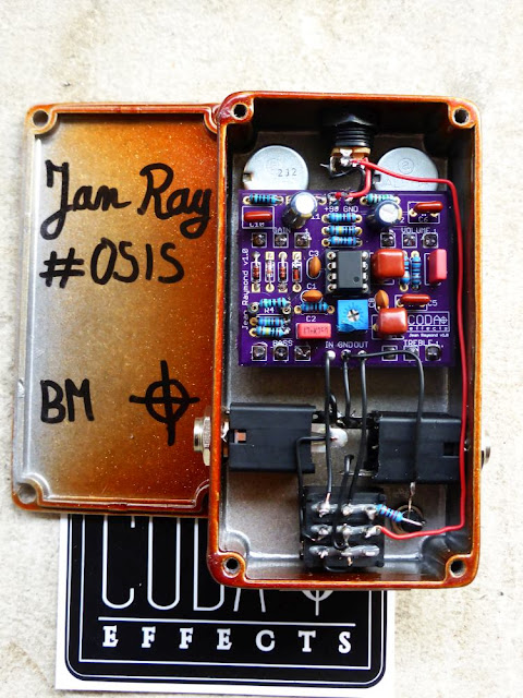
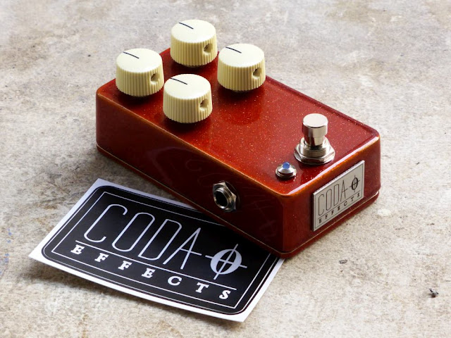
Jan Ray in a 1590B with Coda Effects PCB!

Here my latest version of the Jan Ray! This time, instead of the 1590BB or the 125B version, I made a smaller 1590B version, using a PCB that I designed! 

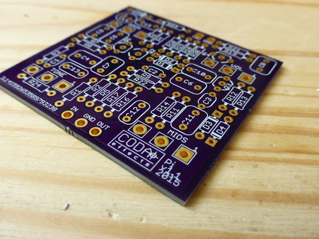
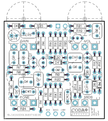
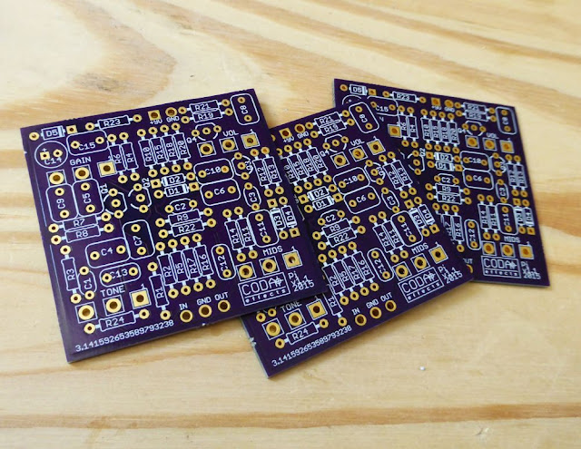
The Jan ray is quite annoying to make on vero, mainly because of the four knobs to wire. A PCB is thus quite helpful to make it easily. Moreover, it allows me to fit it in a 1590B enclosure. Here is the finished pedal:
Vemuram Jan Ray clone

I used the same look as before, with vintage orange sparkle prepainted enclosure, except that it is a 1590B now :)

 Make one yourself

It is quite a simple and fun build to do

Vemuram Jan Ray clone 
I also used a sticker to name it: Golden Hour (vintage overdrive). Photographers will understand! I think it gives a really nice look to this pedal. 

Here is the gutshot:
Vemuram Jan Ray clone
It is the classical circuit of the Jan Ray, with the OP amp, and trimpo for bass content / overall gain. I just changed a few things: R4 is 1.8k instead of 3.3k. This mod allows you to have low gain settings, nice if you want to use this pedal as a clean boost, or just to modify your sounds. Playing with the pedal, I realized you can "stratify" your sound easily by adding trebles and removing bass. Sounded very good with my P90 guitar.

Another modification I did was to replace the OP amp (LM1458) with a Burr brown OPA2134. I think it "soften" a bit the saturation. A nice touch to it.

I am currently testing other mods, with the diodes (LED, compressed...etc.), treble filter (to have less trebles maybe), gain of the last OP amp (too much volume for me on this pedal)

I just made a circuit guide of it to help you understand what does what. The Big muff page has this kind of circuit guide, and I find it very helpful. I hope that you like it, let me know what you think!
Jan Ray Timmy schematic circuit guide
If you want to experiment, socket the component you are interested in modulating, and try different values! Read the circuit analysis I made for more infos.

Sound samples !

LPB1 boost

Remember my LPB1 PCBs? I finally built one! As the PCB is quite small, I decided to make my first 1590A build. Here it is:
LPB1 boost clone 1590A
Simple one knob boost, with quite a lot of gain. I used a 2n5088, which provides already quite a lot of gain. It is a simple volume boost, quite transparent that can be used to make your amp saturate a bit more, or to simply increase the volume of your guitar if you use it in your amp loop.
LPB1 boost clone 1590A
This is my first 1590A, and everything went better than expected. I was afraid that I would not have enough space inside such a tiny box to make all the component AND the circuit fit, but it was OK.

Some advice to make it easier:
  • Use PCB mount 3PDT. They are a bit smaller than "normal" 3PDT and let you a bit more space.
  • Use semi-enclosed jack like Lumberg KLBM3 jacks. They are a bit smaller and easier to use than open jacks like the one I used.
  • use 9mm pots.
Madbean pedals has issued a very nice guide to explain you all the tricks and tips about 1590A builds (pdf). I managed to make it, not the most impressive 1590A build ever, but nice though:
LPB1 boost clone 1590A

How does it sound?


Well, it is a simple clean boost. So you can either use it as a volume boost in front of your amp (if set clean), or in the FX loop, or to increase the gain of your amp if you have set it crunchy. You can also use it before a dirt pedal to increase the saturation of it.
I am planning on testing it in front of different builds. I already tried it in front of a Jan Ray build, making it basically a Tim, nice to have 2 gains settings in one pedal. I also want to try it in front of a Big Muff, like in the Musket Fuzz... I think it can fit in approximately any guitar pedal!


Circuit guide


I already did a circuit analysis of the LPB1 booster. However, I realized that sometimes, it is easier for beginners to understand the role of each component with an infographic, like the circuit guide of the Big Muff page.
Here is the one of the LPB1 booster :
LPB1 circuit guide schematic

Let me know if you like this kind of representations, I can try to update old circuit analysis with circuit guides like this one!

Big Muff mods and tweaks

Big Muff mods and tweaks
I recently noticed that a page I referred to a lot just disappeared from internet... It is the Big Muff mods and tweaks page that was deleted recently.

Fortunately for us, there are some "internet archives" website that keep it alive for a while. In order to keep it alive, I added it here. I also added a list of personnal mods that work quite well, and some notes about mods I already tried.
Modded Big Muff

Easy mods

Diodes mods

The Big muff contains 4 diodes (2 pairs of diodes), that clip the signal to create gain, and compress the signal. Changing these diodes can change the compression and gain of the pedal drastically:
  • Silicon diodes: these are the original diodes used in the Big Muff. Usually, they are 1n4148 type diodes, and gives the Big Muff reference tone: gainy, compressed yet crispy and tight distortion.
  • Germanium diodes: germanium diodes will cut the sound more. You will have a more gainy, more compressed saturation, but also you will loose quite a bit of output volume. No germanium diodes were used in original Big Muffs.
  • LEDs: LEDs are also diodes and can clip the signal. Red diodes clip more the signal compared to yellow, blue ones. There will be less gain, less compression and also more volume output. It gives to the Big Muff a nice "overdrive" feel, with a bit more dynamics. Note from Coda Effects: I tried it on this Big Muff variant, I really like it! It gives a lot of dynamics to the muff.
  • FET / MOSFET: if you tie together the drain and gate of FET / MOSFET transistors, they will behave like diodes. Sound is similar to silicon diodes, a bit smoother.
  • Remove the first pair of diodes, and you have got a Colorsound Supa Tonebender! The unit will be louder, with more bass, but still quite compressed. Great trick for bass players.
  • Remove the two pairs of diodes: great trick! By removing the diodes from the unit now sound if fed back. Result: more volume (LOUD!), less compression, less gain and a more open (overdrive) sound. In my Dolmen Fuzz, I removed all the diodes with the central position of the switch: massive spurry sound!
A good way to see what is your favorite combination is to use sockets for the diodes. You can also use switches to change the diodes. Here is an example with silicon diodes and LEDs :

https://encrypted-tbn1.gstatic.com/images?q=tbn:ANd9GcQ0QI4Q-S9aX9rG9KEqwSo3ptk_agK8b6PPqT39kSRC2bEBQu1j

Works really well and it gives you multiples choices. With 2 of these on-on-on switches you can choose between no diodes or 2 different diodes set for each gain stage!


Emitter mod

Each transistor's emitter of the gain stages of the Big Muff is linked to the ground by a resistor (either 100R or 390R, R12 & R16). Removing the resistors will increase the "gainy-ness" of the pedal, increasing the resistors will lower it.

Resistor mod Each of the gain stages has a limiting resistor on the start of it (R8 & R13). These are 8.2k (8k2) or 10k in different models. By diminishing these values the unit gets more gainy. (Note from Coda Effects: beware! There is a typo on the original Big Muff mods and tweaks text. Diminish it for more gain)


Creamy Dreamer

Basically the combination of the Emitter mod and the Resistor mod.


Noise gate mod

This mod will quieten the Muff while not playing, thus a noise gate. To do this, add a 100k trimpot (wired as a variable resistor) parallel to the 100k to ground of the second gain stage (R14). The trimpot can be adjusted to taste to get the max noise gate effect.


Coupling caps mod

The Muff has a lot of coupling caps (C1, 3, 4, 7, 16, 12 & 13). Coupling caps are next to the block of DC also a way to set the frequency response of the unit. 

Enlarging these caps give the unit more bass, making em smaller give the unit more treble. Experiment with em. Also the sort of caps can make a difference in noise, feeling and authenticity. Old Muffs used ceramic coupling caps; using film caps here won't give you the same sound


High roll-off mod

Notice those small ceramic caps on 3 of the transistor stages? They are used to roll of excessive highs. Normally they are 470 pF (C2, 5 & 8) but larger values roll of more highs. You can also remove em for a great result.


Clipping caps mods

Next to the diodes is also a cap placed (C6 & 9). This cap determines the frequency band the unit clips. Enlarging this cap will make it clip more low notes, make it smaller for more high end clipping.


Transistor mods

The Muff uses four transistors and the type and choice of these transistors will affect the sound greatly. The higher the gain, the more the unit will focus on the high end / treble. Some known examples:
  • The Russian Muff uses E type transistors (newer ones use BC549C's though) which has a Hfe of around 500. I used BC184's as a great replacement of these transistors.
  • The NYC Muffs usually use 2N5088's or BC550's with a Hfe of around 800.
  • The Little Big Muff uses 2N5962 with a Hfe of around 1500 - 2000.
The Russian sounds darker due to the low gain. Knowing this, we can change the sound of a muff greatly by replacing the transistors. Small tip: use sockets when changing transistors. This way the transistors are not damaged by the soldering and swapping is much much easier. Some nice ones:
  • 2N5133's: used in Triangle ones (the NOS versions tend to sound even better then newer ones) as FS36999's. Very nice sound, smooth, warm, open.One of my favs! Note from Coda Effects: I would not use these ones. They are really rare and expensive. I am not sure that they really sound better... I would try to find something similar in hfe (around 100-400).
  • BC239's: also used in a bunch of Muffs around. Slight less gain as the above named but this gives the Muff quite a nice touch.
  • 2N5087's: PNP transistors instead of the above named NPN (more usualble). To use these you need to reorient some of the caps and change the + and - of the battery (called positive ground). Although they must be identical to 2N5088's they were used in some old models and do sound different.
  • BC141's: ultra low Hfe (around 100) and not suited for anyone out there. More bass, less gain but a very different sound.
  • MPSA13's: ultra high Hfe (around 10.000). Nice touch for some more gain.
Experiment! Use four of the same transistors or try to mix. For example I like a Muff with 5133's for the clipping stages and MPSA13's for the buffer stages.

Note from Coda Effects: I also experimented with a few transistors, here is my feedback about this:
  • The first transistor is the one that will define the most of the gain of your unit. Higher hfe = more gain, but also more trebles... I tried a few ones:
    • 2n5089: high gain, but also gives a "gritty" touch to the muff that I do not really like. Also quite noisy
    • 2n5088: nice sound, gainy unit, but less noisy and agressive trebles than 2n5089. I really like it and use it often.
    • 2n2222A: low gain, gives more bass and smoother sound. Beware: polarity is reversed compared to 2n5089.
    • MPSA18: extreme gain! I would suggest to increase emitter resistor to limit gain (especially for noise issues), but you can have a nice "doomy" muff with it!
    • 2n3904/BC549C: great for a low gain Muff.
  • The two transistors of the gain stages play a bit more with compression. I usually use low hfe. 2n2222 are really nice for this use. 2n5088 can also do the job.
  • The last transistor will define the final output volume of the unit. I like to have quite a lot of output volume, so I prefer to use high hfe transistor for the last stage, like 2n5089, or MPSA18.

Feedback mod

This mod is also not for anyone. It will give the Muff a weird drone note that will interact with the notes played resulting in octaves (up and down), nintendo sounds or a huge MUSH. Can sound quite nice and interesting!!!!! The mod is done with a feedback loop: connecting two points together and letting signal flow back. I found two of these loops in my Muff (note: more can be there; try for yourself!)
  1. Connect the emitter of Q3 with the emitter of Q2 through a switch (so you can turn the loop off). The sustain will be on full when this mod is engaged.
  2. Connect the collector of Q3 with the collector of Q1 through a switch. The sustain now can be varied by the sustain knob.
Great addition: add a 1M potmeter in the loop (wired as a variable resistor) or, even better!!, a LDR (light dependent resistor). With the latter, you can control the amount of feedback with the light on stage / with your foot shading the LDR from the light. Cool!

Note from Coda effects: this is really cool, but I will suggest to use a momentary footswitch. If not, you can be quickly bored with the noisy issues that will rise from this mod. However, from times to times (beginning of a song), it is a killer mod to use!


Pictures:

NYC muff:
BMP ref pic 37

BMP ref pic 38


Russian muff: (Note from Coda Effects: these units are getting rarer and rarer, I would not modify it)

BMP REF PIX 39


Tonestack mods

The Big Muff Pi is legendary due to his tone section; only one knob to select between a bass, treble or in-between setting. The overall sound of this tone knob is the loved / hated mid cut.

Some Versions:

  • Triangle version: R1=33k, C1=4n, R2=33k, C2=10n;
  • Ramshead version: R1=33k, C1=4n, R2=22k, C2=10n;
  • 1975 version: R1=39k, C1=4n, R2 = 22k, C2=10n;
  • 1977 opamp version (1): R1=5.6k, C1=100n, R2=1.2k, C2=120n;
  • 1977 opamp version (2): R1=8.2k, C1=100n, R2=1.2k, C2=120n;
  • Green Russian version: R1=20k, C1=3.9n, R2=22k, C2=10n;
  • Late model: R1=39k, C1=4n, R2=100k, C2=10n
  • Reissue version: R1=22k, C1=3.9n, R2=22k, C2=10n;
  • Little Big Muff version = reissue version.
And then some different mods:
  • Swollen Pickle: R1=33k, C1=3.3n, R2 = 22k, C2=47n;
  • Flat mids: R1=33k, C1=5.6n, R2=33k, C2=5.6n; 

Tone stack bypass mod

By bypassing the tonestack the tonestack has no influence anymore on the sound thus does not color the signal in it's own way. Great way to get a more middy tone from your Muff. As the tone stack also cuts volume you get a huge volume increase

Tone stack complete mod

One of my most fav mods. Remove the tone stack altogether from the Muff and place a three band EQ circuit in it's place. Works like a charm and gives you more control over the sound! I also once added a Boss GE-7 in this place to give total control over the sound.

Read my post about the Big Muff tonestack for more infos about how the tonestack works and what mods you can do.


Bonus mods (Coda Effects)

Here are other easy mods and tweaks that can give a nice touch to a Big Muff:

Input Resistor / Capacitor:

The input resistor (R1) and capacitor (C1) defines how much signal enters the pedal, ie the overall gain of the unit. It also forms a filter that will allow some frequencies to go in or not.

Increasing the value of the resistor will lower the gain, and lower treble content of the pedal.
Increasing the value of the capacitor will increase the amount ot bass and the overall gain of the unit.

I like to use a switch to choose between a high gain bassy setting, and a lower gain treblier setting.
A smaller value in C1 also helps reducing noise. I used this mod on this Big Muff for instance.


LPB1 before the muff circuit

Adding a LBP1 before the muff circuit can allow you to add an extra gain / bass amount to the muff. It really add some "heaviness" to the distortion. You can do it on a veroboard, with a trimmer or external gain potentiometer. I want to use the PCB I made recently to try this mod. The musket from Blackout Effectors uses this trick. With a simple 3PDT wiring, you can make it activable or not.


Germanium transistors in the distorsion stage

It can smoothen the Big Muff a bit, but remember to have a high gain last stage to recover enough volume. This is used in the Hoof fuzz from EQD. I am not super found of this mod, but you can try it out if you want! Remember to use NPN germanium transistors.


Voltage starver mod

You can emulate a dead battery, that will give a very peculiar sound to the muff: it cleans up a bit, and the circuit starts to sound "gated", and "stutters" a bit because it does not have enough power to work correctly. I would suggest to use this schematic:

 Afficher l'image d'origine
Just connect the output voltage to the voltage input of your Big Muff.


18V Muff 

Beware: I never tested it on a EHX, and I do not know if the stock pedal can handle 18V... If you have already test it, tell me. However, if you have made a clone with capacitors that can handle 18V or more, you can try to use a MAX1044 as a voltage doubler to supply your Big Muff with 18V instead of 9V!


Here it is! I hope that you liked it, good luck with experimenting!
If this article was useful, you can thank me by liking the Coda Effects Facebook Page!
Big Muff circuit going to fab!

Here is my new Big Muff PCB!Big Muff PCB
Remember when I was telling you about PCB development? (yes, long time ago...) I finally finished one! It took me a lot of time, but now I am satisfied with my layout:
Big Muff PCB layout
As some of you recognized, this is a Big Muff circuit! I decided to add an optional forth knob: the mid knob. I can decide whether I want to add it or not, simply by adding a jumper if not (and then, the tone potentiometer can be wired in the center of the pedal). Maybe I will add another optional feedback mod, allowing to connect Q1 emitter to Q3 emitter via a switch. It creates a nice noisy feedback, ideal for sound experimentations...

The circuit is exactly the same as a classical Big Muff, I just added the mid knob in the tone stack, and some components for polarity protection and voltage stabilization. (on the top-left part of the PCB) I will rename the components so their number will be the same as the one used on the Big Muff Page, so you can easily make any version of the Big Muff you like, or modify it with their great circuit guide.

Capacitors sizes were chosen bigger than needed, so they can be swapped with other value to fit any Big Muff model (Russian, Ram's Head, ...etc). Note the funky logo I made because OshPark is not able to use imported images...  Anyway, it is still nice!

I receive the first batch of prototypes:
Big Muff printed circuit board

It is a very compact build! It can fit a 1590B enclosure (well, I hope so...), or at least a 125B with top mounted jack. For now, I ordered a test batch of 3 PCB in oshpark, and I plan to test it as soon as possible! If it works correctly, I think I will produce a small serie of PCB.

    As you may know, PCB are cheaper if ordered in large quantities. If you are interested in buying one PCB (or more!), send me an email, so I can adjust the number of PCB I will order! Price will be around 5-8 euros for the first batch (depending on the number of people interested), with a 1 euro shipping cost for France, and 3 euros abroad.

I first designed this PCB for personal use, but it can be a win-win situation if people are interested.

For now, I am thinking about the logo I will use, I thought of this:
I noticed that the "Pi" symbol, looked like a lot a Dolmen... Which is also convenient for a Fuzz that has been used by many stoner guitarists, including ones disguised as druids (Sunn o))), anyone ?). Maybe I will have it laser cutted in black or red (maybe purple for a "violet era" rams head), in order to have 2/3 different version. A bare aluminium version with the red logo that will be the "vintage correct" version, following a classic 73 ram's head fuzz schematic, and a black logo on a black or dark green (russian) box for a "doomy" version, very bassy and gainy.

Let me know what you think about it, post a comment!

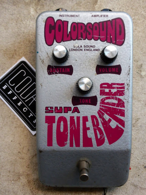
Vintage Colorsound Supa Tonebender (1973)

A nice reader of the blog lend me this super cool Colorsound "Supa" Tonebender, from 1973! Someone he knows found it in his garage and gave it to him (true story!). Colorsound is an old English brand that produced pedals during the late sixites. One of the most famous pedals they have produced is the Tonebender.

The Tonebender is a fuzz that existed in several versions: Mk1, Mk1.5 (yes!), MK2 (famous because used by Jimmy Page a lot), MK3 (with a third knob)... All versions are really different, and the circuit changed a lot from one version to another. You did not know the Tonebender? Read my post about the different types of fuzz! This "Supa" Tonebender is a version of the tonebender that appeared in 1973. Here it is:
Colorsound supa tonebender fuzz
Nice looking pedal huh? The enclosure is huuuge! At that time, guitar players did not have pedalboards, and circuits were rather big (we will see it later). Manufacturers preferred to make reliable, kick-proof pedals made for the stage and live situations.

It has 3 knobs: volume, sustain and tone... Does it evoke something to you? Yes, you are right: Big Muff! This "Supa" Tonebender is indeed a Big Muff clone! It is a slightly modified Big Muff Ram's head "violet era" as we will see later.
Colorsound supa tonebender fuzz
(note the inverted "amplifier" and "instrument" input, like on vintage fuzz faces).

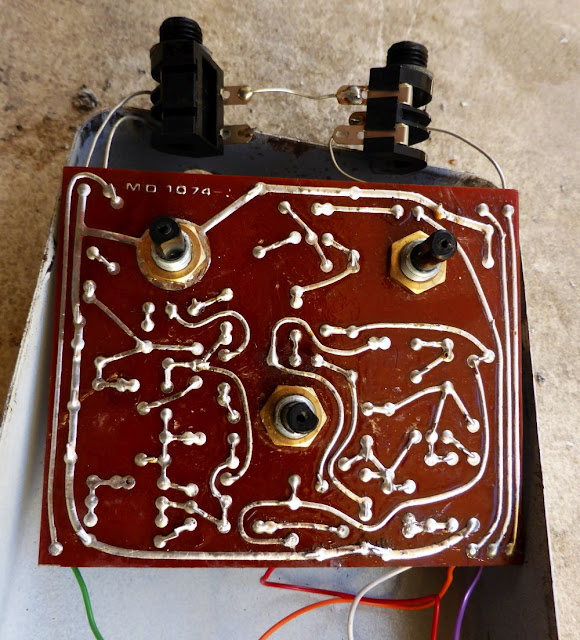
Inside, we find a nice vintage brown circuit! Pots are "made in UK" (globalization was not really happening in 1973 ^^), carbon-film resistors, and some funny old film capacitors! Everything is wired with a 2PDT, with no LED (that were not available commercialy yet!)
Colorsound Supa Tonebender circuit
We can see 4 transistors, 470pF capacitors, everything that is included in a classical Big Muff circuit. Transistors are BC169B, silicon transistors with a hfe of about 200-250, which is quite a good range for a Big Muff (nice intermediate between high and low gain). You can still find some on ebay, contrary to EHX 2n5133, but are a bit expensive (2/3 euros for one transistor...).

If you look carefully, you can see that there are only 2 diodes... Three components are missing: 2 diodes and the coupling capacitor of the first gain stage. However, there are still holes for them on the board!
Colorsound Supa Tonebender circuit transistors
It seems like Colorsound staff wanted to copy the Big Muff circuit entirely, and then changed their mind (ethics?), and remove the 2 diodes and coupling cap of the first gain stage. However on the first versions of the PCB like this one, the holes are still there!

Beneath the PCB, it is quite funny looking! It is a really curvy PCB, traced by hand, that evokes the first PCB of the 60s/70s. The PCB of the first Dallas Arbiter Fuzz face looks like this PCB.
Colorsound Supa Tonebender circuit
Nice looking pedal, vintage and all original!


How does it sound?


The gain potentiometer is a bit noisy, and there is a slight volume drop when pushed to max. It is probably a small deffect of the pots, that are usually the first components that get damaged. Unfortunatelly, these potentiometers are no longer in production, and not easy to replace without damaging / definitely alterate the pedal. I would rather have a bit of noise when turning the knobs than modifying heavily this cool vintage pedal!


It sounds a lot like a Big Muff: compressed, heavy sounding device! The removed diodes of the first stage make it louder in volume, but it is still quite compressed and heavy sounding. Lot of bass too! Like a lot of Big Muff, it does not clean very well with the volume knob.


Tracing the circuit


Ok, lets trace the circuit of this wonderful pedal! We want to trace the circuit schematic with the component's nature and values. Usually, I use GIMP (or photoshop, as you want), to make this kind of pictures:
Supa tonebender circuit
To do that, I take a picture of the top and bottom of the circuit. I make the top part transparent a bit, reverse the colors of the bottom part, and adjust with the different tools of GIMP (scale and perspective)


You can see that the empty spaces with the holes let for the missing components are still connected to the circuit via the PCB. Thus, it should be possible to "mod" this Supa Tonebender to transform it into a Ram's Head violet era! However, I prefer to let it as is, all original!

Ok, so let's go! let's trace the global circuit:
Supa tonebender circuit

OK know that we have all the values, the ground and +9V buses marked, we can start tracing the circuit. As we know that it is inspired by a Big Muff, we can look at the classical schematic of the Big Muff to help us.

The input goes through a 33k resistor, then a 0.1uF capacitor. The capacitor is then connected to a 100k resistor connected to ground, that is also connected to the first transistor collector and a 470k resistor... It is the first gain stage of a Big Muff!
Beware, BC169B have a weird pinout layout!
BC169B pinout
So the 100k resistor is connected to the base of the transistor. Here is the traced schematic:
Colorsound Supa Tonebender schematic
Yes, it is a slightly modified Big Muff... Nothing really new! You can easily make one with a Big Muff PCB, just remove the clipping diodes and capacitors on the first stage. That is exactly what Colorsound did after all ;)

I hope that this will be useful to you!
If you want to know how it works, read my article about the circuit analysis of the Big Muff.

Black Keys's Big Muff: dealing with mids frequencies

Another Big Muff clone! This time, I was inspired by the Black Keys (if you do not know this band, go check it out, it is awesome!). Dan Auerbach, the guitarist/singer, uses a lot of fuzz effects, and especially a green russian Big Muff, and a Earthquaker Devices Hoof (a Big Muff variant with some interesting modifications as we will see later).

So I decided to basically mix these two variants in one Big Muff! Here it is, a 4-knobbed Big Muff:


LPB1 mini PCB !

The LPB1 (Line Power Boost 1) is a boost pedal that was commercialized in 1968 by Electro Harmonix. It is the first boost pedal using a silicon transistor. Indeed, previous boosts like the Dallas Rangemaster Treble Booster were using germanium transistors. Another novelty with this pedal was that it was boosting all frequencies and not only trebles, making it the first clean boost available!
 vintage 1968 LPB1
The circuit is really the most simple one you can imagine for a boost:
LPB1 schematic
First, there is a 0.1uF coupling capacitor that prevents parasitic DC current from the guitar to go in the circuit. With the R2 resistance, it forms a high pass filter : by changing its value, you can modulate the amount of bass going through the circuit. If you increase C1 value, more bass will go through, and vice versa.

Then, there are two resistors forming a voltage divider (R2 and R1), to provide a certain voltage to the base of the transistor. Here it is : R2/(R2+R1)x9V = 43/(43+430)x9=0,81V at the transistor's base.

The silicon transistor is a 2n5088 (originally a 2n5133 - same transistors that were used in the Big Muff later), wired as a common emitter. R4 and R3 will define the amount of amplification. If you increase R4, amplification will be larger. If you increase R3, there will be less gain.
A second 0.1uF coupling capacitor that prevents DC current from the battery to go out of the circuit. Finally, a 100k potentiometer wired as a variable resistor defines the final volume.

If you look carefuly, you can see that the last stage of the Big Muff circuit is exactly the same! A LPB1 circuit is used to increase the final volume.

Indeed, this circuit can be used in a lot of different effects to boost the entry or final level. A fun thing to do is to add a LPB1 boost before a saturation effect to increase the gain. It is very fun on a Big Muff (like in the Musket Fuzz or Supercolider fuzz), or on a Tube screamer (like in the Fulltone Fulldrive)!

In order to be able to add this little circuit when I want, or to test it on several pedals, I decided to make a small PCB that allows you to add a "boost" knob on every pedal you want. There is a "in" and a "out" pad that allows you to place it anywhere in a circuit:
EHX LPB1 PCB line power boost
I will test it on a Big Muff or a Jan Ray! I could also try to see if it can fit a Hammond LB enclosure (super small squared enclosures like the one I used for my Strymon Favorite switch) Note that there is no voltage stabilization or polarity protection system on this board (too small, not enough space for it!), so do not hesitate to wire a 100uF capacitor between the two lugs of your power supply input.

I should receive all the parts to test it soon...